Contents of this page is copied directly from AWS blog sites to make it Kindle friendly. Some styles & sections from these pages are removed to render this properly in 'Article Mode' of Kindle e-Reader browser. All the contents of this page is property of AWS.
Page 1|Page 2|Page 3|Page 4
Offset lag metric for Amazon MSK as an event source for Lambda
=======================
This post written by Adam Wagner, Principal Serverless Solutions Architect.
Last year, AWS announced support for Amazon Managed Streaming for Apache Kafka (MSK) and self-managed Apache Kafka clusters as event sources for AWS Lambda. Today, AWS adds a new OffsetLag metric to Lambda functions with MSK or self-managed Apache Kafka event sources.
Offset in Apache Kafka is an integer that marks the current position of a consumer. OffsetLag is the difference in offset between the last record written to the Kafka topic and the last record processed by Lambda. Kafka expresses this in the number of records, not a measure of time. This metric provides visibility into whether your Lambda function is keeping up with the records added to the topic it is processing.
This blog walks through using the OffsetLag metric along with other Lambda and MSK metrics to understand your streaming application and optimize your Lambda function.
Overview
In this example application, a producer writes messages to a topic on the MSK cluster that is an event source for a Lambda function. Each message contains a number and the Lambda function finds the factors of that number. It outputs the input number and results to an Amazon DynamoDB table.
Finding all the factors of a number is fast if the number is small but takes longer for larger numbers. This difference means the size of the number written to the MSK topic influences the Lambda function duration.

Example application architecture
- A Kafka client writes messages to a topic in the MSK cluster.
- The Lambda event source polls the MSK topic on your behalf for new messages and triggers your Lambda function with batches of messages.
- The Lambda function factors the number in each message and then writes the results to DynamoDB.
In this application, several factors can contribute to offset lag. The first is the volume and size of messages. If more messages are coming in, the Lambda may take longer to process them. Other factors are the number of partitions in the topic, and the number of concurrent Lambda functions processing messages. A full explanation of how Lambda concurrency scales with the MSK event source is in the documentation.
If the average duration of your Lambda function increases, this also tends to increase the offset lag. This lag could be latency in a downstream service or due to the complexity of the incoming messages. Lastly, if your Lambda function errors, the MSK event source retries the identical records set until they succeed. This retry functionality also increases offset lag.
Measuring OffsetLag
To understand how the new OffsetLag metric works, you first need a working MSK topic as an event source for a Lambda function. Follow this blog post to set up an MSK instance.
To find the OffsetLag metric, go to the CloudWatch console, select All Metrics from the left-hand menu. Then select Lambda, followed by By Function Name to see a list of metrics by Lambda function. Scroll or use the search bar to find the metrics for this function and select OffsetLag.

OffsetLag metric example
To make it easier to look at multiple metrics at once, create a CloudWatch dashboard starting with the OffsetLag metric. Select Actions -> Add to Dashboard. Select the Create new button, provide the dashboard a name. Choose Create, keeping the rest of the options at the defaults.

Adding OffsetLag to dashboard
After choosing Add to dashboard, the new dashboard appears. Choose the Add widget button to add the Lambda duration metric from the same function. Add another widget that combines both Lambda errors and invocations for the function. Finally, add a widget for the BytesInPerSec metric for the MSK topic. Find this metric under AWS/Kafka -> Broker ID, Cluster Name, Topic. Finally, click Save dashboard.
After a few minutes, you see a steady stream of invocations, as you would expect when consuming from a busy topic.

Data incoming to dashboard
This example is a CloudWatch dashboard showing the Lambda OffsetLag, Duration, Errors, and Invocations, along with the BytesInPerSec for the MSK topic.
In this example, the OffSetLag metric is averaging about eight, indicating that the Lambda function is eight records behind the latest record in the topic. While this is acceptable, there is room for improvement.
The first thing to look for is Lambda function errors, which can drive up offset lag. The metrics show that there are no errors so the next step is to evaluate and optimize the code.
The Lambda handler function loops through the records and calls the process_msg function on each record:
def lambda_handler(event, context):
for batch in event['records'].keys():
for record in event['records'][batch]:
try:
process_msg(record)
except:
print("error processing record:", record)
return()
The process_msg function handles base64 decoding, calls a factor function to factor the number, and writes the record to a DynamoDB table:
def process_msg(record):
#messages are base64 encoded, so we decode it here
msg_value = base64.b64decode(record['value']).decode()
msg_dict = json.loads(msg_value)
#using the number as the hash key in the dynamodb table
msg_id = f"{msg_dict['number']}"
if msg_dict['number'] <= MAX_NUMBER:
factors = factor_number(msg_dict['number'])
print(f"number: {msg_dict['number']} has factors: {factors}")
item = {'msg_id': msg_id, 'msg':msg_value, 'factors':factors}
resp = ddb_table.put_item(Item=item)
else:
print(f"ERROR: {msg_dict['number']} is >= limit of {MAX_NUMBER}")
The heavy computation takes place in the factor function:
def factor(number):
factors = [1,number]
for x in range(2, (int(1 + number / 2))):
if (number % x) == 0:
factors.append(x)
return factors
The code loops through all numbers up to the factored number divided by two. The code is optimized by only looping up to the square root of the number.
def factor(number):
factors = [1,number]
for x in range(2, 1 + int(number**0.5)):
if (number % x) == 0:
factors.append(x)
factors.append(number // x)
return factors
There are further optimizations and libraries for factoring numbers but this provides a noticeable performance improvement in this example.

Data after optimization
After deploying the code, refresh the metrics after a while to see the improvements:
The average Lambda duration has dropped to single-digit milliseconds and the OffsetLag is now averaging two.
If you see a noticeable change in the OffsetLag metric, there are several things to investigate. The input side of the system, increased messages per second, or a significant increase in the size of the message are a few options.
Conclusion
This post walks through implementing the OffsetLag metric to understand latency between the latest messages in the MSK topic and the records a Lambda function is processing. It also reviews other metrics that help understand the underlying cause of increases to the offset lag. For more information on this topic, refer to the documentation and other MSK Lambda metrics.
For more serverless learning resources, visit Serverless Land.
Expanding cross-Region event routing with Amazon EventBridge
=======================
This post is written by Stephen Liedig, Sr Serverless Specialist SA.
In April 2021, AWS announced a new feature for Amazon EventBridge that allows you to route events from any commercial AWS Region to US East (N. Virginia), US West (Oregon), and Europe (Ireland). From today, you can now route events between any AWS Regions, except AWS GovCloud (US) and China.
EventBridge enables developers to create event-driven applications by routing events between AWS services, integrated software as a service (SaaS) applications, and your own applications. This helps you produce loosely coupled, distributed, and maintainable architectures. With these new capabilities, you can now route events across Regions and accounts using the same model used to route events to existing targets.
Cross-Region event routing with Amazon EventBridge makes it easier for customers to develop multi-Region workloads to:
Centralize your AWS events into one Region for auditing and monitoring purposes, such as aggregating security events for compliance reasons in a single account.
Replicate events from source to destinations Regions to help synchronize data in cross-Region data stores.
Invoke asynchronous workflows in a different Region from a source event. For example, you can load balance from a target Region by routing events to another Region.
A previous post shows how cross-Region routing works. This blog post expands on these concepts and discusses a common use case for cross-Region event delivery – event auditing. This example explores how you can manage resources using AWS CloudFormation and EventBridge resource policies.
Multi-Region event auditing example walkthrough
Compliance is an important part of building event-driven applications and reacting to any potential policy or security violations. Customers use EventBridge to route security events from applications and globally distributed infrastructure into a single account for analysis. In many cases, they share specific AWS CloudTrail events with security teams. Customers also audit events from their custom-built applications to monitor sensitive data usage.
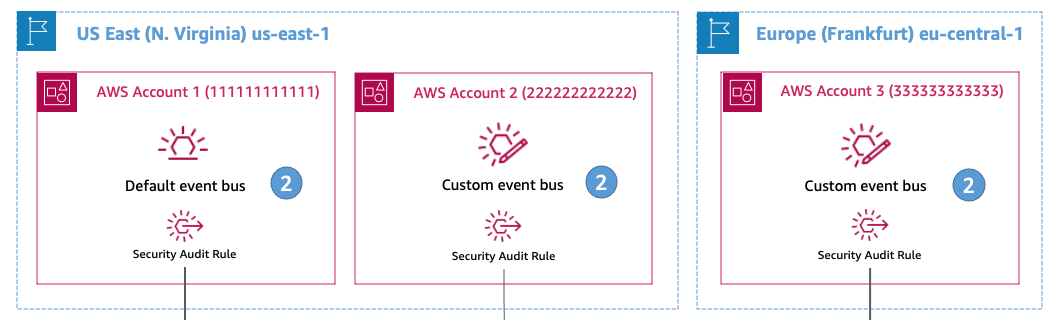
In this scenario, a company has their base of operations located in Asia Pacific (Singapore) with applications distributed across US East (N. Virginia) and Europe (Frankfurt). The applications in US East (N. Virginia) and Europe (Frankfurt) are using EventBridge for their respective applications and services. The security team in Asia Pacific (Singapore) wants to analyze events from the applications and CloudTrail events for specific API calls to monitor infrastructure security.

To create the rules to receive these events:
- Create a new set of rules directly on all the event buses across the global infrastructure. Alternatively, delegate the responsibility of managing security rules to distributed teams that manage the event bus resources.
- Provide the security team with the ability to manage rules centrally, and control the lifecycle of rules on the global infrastructure.
Allowing the security team to manage the resources centrally provides more scalability. It is more consistent with the design principle that event consumers own and manage the rules that define how they process events.
Deploying the example application
The following code snippets are shortened for brevity. The full source code of the solution is in the GitHub repository. The solution uses AWS Serverless Application Model (AWS SAM) for deployment. Clone the repo and navigate to the solution directory:
git clone https://github.com/aws-samples/amazon-eventbridge-resource-policy-samples
cd ./patterns/ cross-region-cross-account-pattern/
To allow the security team to start receiving accounts from any of the cross-Region accounts:
1. Create a security event bus in the Asia Pacific (Singapore) Region with a rule that processes events from the respective event sources.

For simplicity, this example uses an Amazon CloudWatch Logs target to visualize the events arriving from cross-Region accounts:
 SecurityEventBus:
Type: AWS::Events::EventBus
Properties:
Name: !Ref SecurityEventBusName
# This rule processes events coming in from cross-Region accounts
SecurityAnalysisRule:
Type: AWS::Events::Rule
Properties:
Name: SecurityAnalysisRule
Description: Analyze events from cross-Region event buses
EventBusName: !GetAtt SecurityEventBus.Arn
EventPattern:
source:
- anything-but: com.company.security
State: ENABLED
RoleArn: !GetAtt WriteToCwlRole.Arn
Targets:
- Id: SendEventToSecurityAnalysisRule
Arn: !Sub "arn:aws:logs:${AWS::Region}:${AWS::AccountId}:log-group:${SecurityAnalysisRuleTarget}"
In this example, you set the event pattern to process any event from a source that is not from the security team’s own domain. This allows you to process events from any account in any Region. You can filter this further as needed.
2. Set an event bus policy on each default and custom event bus that the security team must receive events from.

This policy allows the security team to create rules to route events to its own security event bus in the Asia Pacific (Singapore) Region. The following policy defines a custom event bus in Account 2 in US East (N. Virginia) and an AWS::Events::EventBusPolicy that sets the Principal as the security team account.
This allows the security team to manage rules on the CustomEventBus:
 CustomEventBus:
Type: AWS::Events::EventBus
Properties:
Name: !Ref EventBusName
SecurityServiceRuleCreationStatement:
Type: AWS::Events::EventBusPolicy
Properties:
EventBusName: !Ref CustomEventBus # If you omit this, the default event bus is used.
StatementId: "AllowCrossRegionRulesForSecurityTeam"
Statement:
Effect: "Allow"
Principal:
AWS: !Sub "arn:aws:iam::${SecurityAccountNo}:root"
Action:
- "events:PutRule"
- "events:DeleteRule"
- "events:DescribeRule"
- "events:DisableRule"
- "events:EnableRule"
- "events:PutTargets"
- "events:RemoveTargets"
Resource:
- !Sub 'arn:aws:events:${AWS::Region}:${AWS::AccountId}:rule/${CustomEventBus.Name}/*'
Condition:
StringEqualsIfExists:
"events:creatorAccount": "${aws:PrincipalAccount}"
3. With the policies set on the cross-Region accounts, now create the rules. Because you cannot create CloudFormation resources across Regions, you must define the rules in separate templates. This also gives the ability to expand to other Regions.
Once the template is deployed to the cross-Region accounts, use EventBridge resource policies to propagate rule definitions across accounts in the same Region. The security account must have permission to create CloudFormation resources in the cross-Region accounts to deploy the rule templates.

There are two parts to the rule templates. The first specifies a role that allows EventBridge to assume a role to send events to the target event bus in the security account:
 # This IAM role allows EventBridge to assume the permissions necessary to send events
# from the source event buses to the destination event bus.
SourceToDestinationEventBusRole:
Type: "AWS::IAM::Role"
Properties:
AssumeRolePolicyDocument:
Version: 2012-10-17
Statement:
- Effect: Allow
Principal:
Service:
- events.amazonaws.com
Action:
- "sts:AssumeRole"
Path: /
Policies:
- PolicyName: PutEventsOnDestinationEventBus
PolicyDocument:
Version: 2012-10-17
Statement:
- Effect: Allow
Action: "events:PutEvents"
Resource:
- !Ref SecurityEventBusArn
The second is the definition of the rule resource. This requires the Amazon Resource Name (ARN) of the event bus where you want to put the rule, the ARN of the target event bus in the security account, and a reference to the SourceToDestinationEventBusRole role:
 SecurityAuditRule2:
Type: AWS::Events::Rule
Properties:
Name: SecurityAuditRuleAccount2
Description: Audit rule for the Security team in Singapore
EventBusName: !Ref EventBusArnAccount2 # ARN of the custom event bus in Account 2
EventPattern:
source:
- com.company.marketing
State: ENABLED
Targets:
- Id: SendEventToSecurityEventBusArn
Arn: !Ref SecurityEventBusArn
RoleArn: !GetAtt SourceToDestinationEventBusRole.Arn
You can use the AWS SAM CLI to deploy this:
sam deploy -t us-east-1-rules.yaml \
--stack-name us-east-1-rules \
--region us-east-1 \
--profile default \
--capabilities=CAPABILITY_IAM \
--parameter-overrides SecurityEventBusArn="arn:aws:events:ap-southeast-1:111111111111:event-bus/SecurityEventBus" EventBusArnAccount1="arn:aws:events:us-east-1:111111111111:event-bus/default" EventBusArnAccount2="arn:aws:events:us-east-1:222222222222:event-bus/custom-eventbus-account-2"
Testing the example application
With the rules deployed across the Regions, you can test by sending events to the event bus in Account 2:
- Navigate to the applications/account_2 directory. Here you find an events.json file, which you use as input for the put-events API call.
- Run the following command using the AWS CLI. This sends messages to the event bus in us-east-1 which are routed to the security event bus in ap-southeast-1:
aws events put-events \
--region us-east-1 \
--profile [NAMED PROFILE FOR ACCOUNT 2] \
--entries file://events.json
If you have run this successfully, you see:
Entries:
- EventId: a423b35e-3df0-e5dc-b854-db9c42144fa2
- EventId: 5f22aea8-51ea-371f-7a5f-8300f1c93973
- EventId: 7279fa46-11a6-7495-d7bb-436e391cfcab
- EventId: b1e1ecc1-03f7-e3ef-9aa4-5ac3c8625cc7
- EventId: b68cea94-28e2-bfb9-7b1f-9b2c5089f430
- EventId: fc48a303-a1b2-bda8-8488-32daa5f809d8
FailedEntryCount: 0
- Navigate to the Amazon CloudWatch console to see a collection of log entries with the events you published. The log group is
/aws/events/SecurityAnalysisRule.
Congratulations, you have successfully sent your first events across accounts and Regions!
Conclusion
With cross-Region event routing in EventBridge, you can now route events to and from any AWS Region. This post explains how to manage and configure cross-Region event routing using CloudFormation and EventBridge resource policies to simplify rule propagation across your global event bus infrastructure. Finally, I walk through an example you can deploy to your AWS account.
For more serverless learning resources, visit Serverless Land.
Introducing mutual TLS authentication for Amazon MSK as an event source
=======================
This post is written by Uma Ramadoss, Senior Specialist Solutions Architect, Integration.
Today, AWS Lambda is introducing mutual TLS (mTLS) authentication for Amazon Managed Streaming for Apache Kafka (Amazon MSK) and self-managed Kafka as an event source.
Many customers use Amazon MSK for streaming data from multiple producers. Multiple subscribers can then consume the streaming data and build data pipelines, analytics, and data integration. To learn more, read Using Amazon MSK as an event source for AWS Lambda.
You can activate any combination of authentication modes (mutual TLS, SASL SCRAM, or IAM access control) on new or existing clusters. This is useful if you are migrating to a new authentication mode or must run multiple authentication modes simultaneously. Lambda natively supports consuming messages from both self-managed Kafka and Amazon MSK through event source mapping.
By default, the TLS protocol only requires a server to authenticate itself to the client. The authentication of the client to the server is managed by the application layer. The TLS protocol also offers the ability for the server to request that the client send an X.509 certificate to prove its identity. This is called mutual TLS as both parties are authenticated via certificates with TLS.
Mutual TLS is a commonly used authentication mechanism for business-to-business (B2B) applications. It’s used in standards such as Open Banking, which enables secure open API integrations for financial institutions. It is one of the popular authentication mechanisms for customers using Kafka.
To use mutual TLS authentication for your Kafka-triggered Lambda functions, you provide a signed client certificate, the private key for the certificate, and an optional password if the private key is encrypted. This establishes a trust relationship between Lambda and Amazon MSK or self-managed Kafka. Lambda supports self-signed server certificates or server certificates signed by a private certificate authority (CA) for self-managed Kafka. Lambda trusts the Amazon MSK certificate by default as the certificates are signed by Amazon Trust Services CAs.
This blog post explains how to set up a Lambda function to process messages from an Amazon MSK cluster using mutual TLS authentication.
Overview
Using Amazon MSK as an event source operates in a similar way to using Amazon SQS or Amazon Kinesis. You create an event source mapping by attaching Amazon MSK as event source to your Lambda function.
The Lambda service internally polls for new records from the event source, reading the messages from one or more partitions in batches. It then synchronously invokes your Lambda function, sending each batch as an event payload. Lambda continues to process batches until there are no more messages in the topic.
The Lambda function’s event payload contains an array of records. Each array item contains details of the topic and Kafka partition identifier, together with a timestamp and base64 encoded message.

Kafka event payload
You store the signed client certificate, the private key for the certificate, and an optional password if the private key is encrypted in the AWS Secrets Manager as a secret. You provide the secret in the Lambda event source mapping.
The steps for using mutual TLS authentication for Amazon MSK as event source for Lambda are:
- Create a private certificate authority (CA) using AWS Certificate Manager (ACM) Private Certificate Authority (PCA).
- Create a client certificate and private key. Store them as secret in AWS Secrets Manager.
- Create an Amazon MSK cluster and a consuming Lambda function using the AWS Serverless Application Model (AWS SAM).
- Attach the event source mapping.
This blog walks through these steps in detail.
Prerequisites
Install AWS Command Line Interface (CLI) and AWS SAM CLI.
Install OpenSSL, jq, npm, and Git.
1. Creating a private CA.
To use mutual TLS client authentication with Amazon MSK, create a root CA using AWS ACM Private Certificate Authority (PCA). We recommend using independent ACM PCAs for each MSK cluster when you use mutual TLS to control access. This ensures that TLS certificates signed by PCAs only authenticate with a single MSK cluster.
- From the AWS Certificate Manager console, choose Create a Private CA.
- In the Select CA type panel, select Root CA and choose Next.

Select Root CA
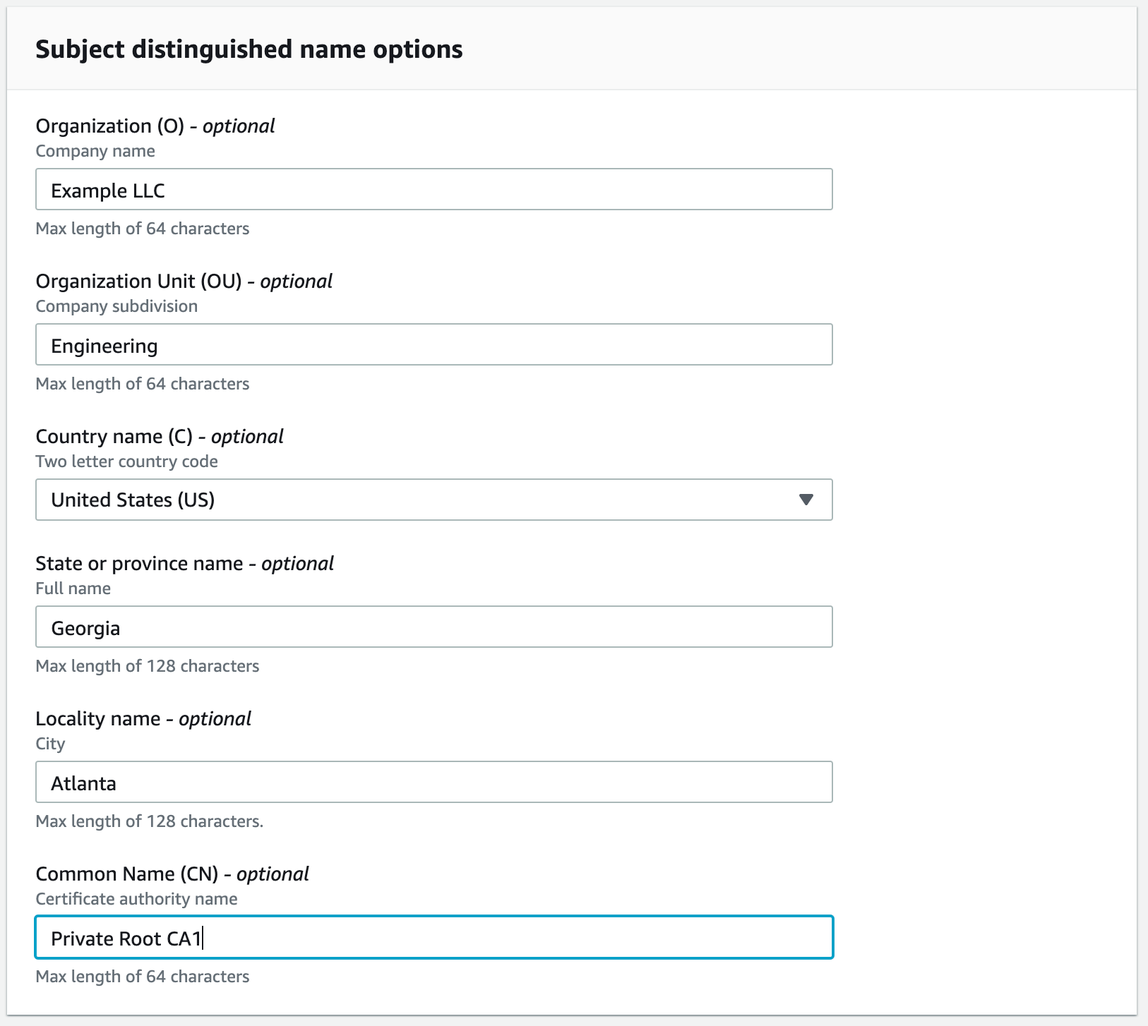
- In the Configure CA subject name panel, provide your certificate details, and choose Next.

Provide your certificate details
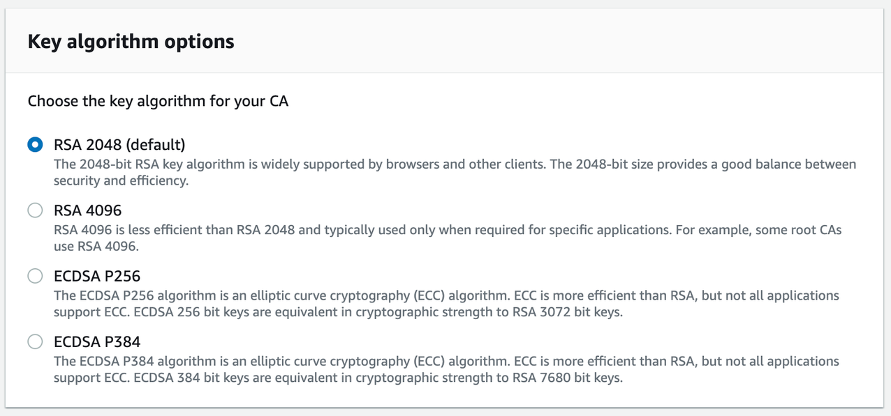
- From the Configure CA key algorithm panel, choose the key algorithm for your CA and choose Next.

Configure CA key algorithm
- From the Configure revocation panel, choose any optional certificate revocation options you require and choose Next.

Configure revocation
- Continue through the screens to add any tags required, allow ACM to renew certificates, review your options, and confirm pricing. Choose Confirm and create.
- Once the CA is created, choose Install CA certificate to activate your CA. Configure the validity of the certificate and the signature algorithm and choose Next.

Configure certificate
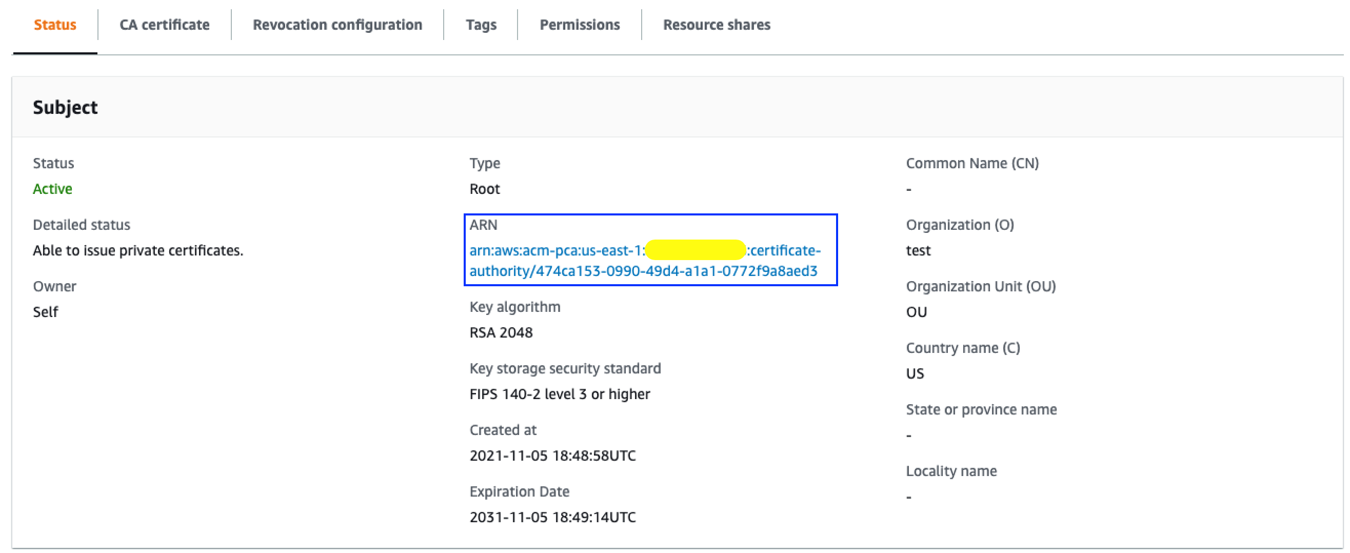
- Review the certificate details and choose Confirm and install. Note down the Amazon Resource Name (ARN) of the private CA for the next section.

Review certificate details
2. Creating a client certificate.
You generate a client certificate using the root certificate you previously created, which is used to authenticate the client with the Amazon MSK cluster using mutual TLS. You provide this client certificate and the private key as AWS Secrets Manager secrets to the AWS Lambda event source mapping.
- On your local machine, run the following command to create a private key and certificate signing request using OpenSSL. Enter your certificate details. This creates a private key file and a certificate signing request file in the current directory.
openssl req -new -newkey rsa:2048 -days 365 -keyout key.pem -out client_cert.csr -nodes
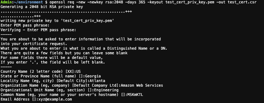
OpenSSL create a private key and certificate signing request
- Use the AWS CLI to sign your certificate request with the private CA previously created. Replace Private-CA-ARN with the ARN of your private CA. The certificate validity value is set to 300, change this if necessary. Save the certificate ARN provided in the response.
aws acm-pca issue-certificate --certificate-authority-arn Private-CA-ARN --csr fileb://client_cert.csr --signing-algorithm "SHA256WITHRSA" --validity Value=300,Type="DAYS"
- Retrieve the certificate that ACM signed for you. Replace the Private-CA-ARN and Certificate-ARN with the ARN you obtained from the previous commands. This creates a signed certificate file called client_cert.pem.
aws acm-pca get-certificate --certificate-authority-arn Private-CA-ARN --certificate-arn Certificate-ARN | jq -r '.Certificate + "\n" + .CertificateChain' >> client_cert.pem
- Create a new file called secret.json with the following structure
{
"certificate":"",
"privateKey":""
}
- Copy the contents of the client_cert.pem in certificate and the content of key.pem in privatekey. Ensure that there are no extra spaces added. The file structure looks like this:

Certificate file structure
- Create the secret and save the ARN for the next section.
aws secretsmanager create-secret --name msk/mtls/lambda/clientcert --secret-string file://secret.json
3. Setting up an Amazon MSK cluster with AWS Lambda as a consumer.
Amazon MSK is a highly available service, so it must be configured to run in a minimum of two Availability Zones in your preferred Region. To comply with security best practice, the brokers are usually configured in private subnets in each Region.
You can use AWS CLI, AWS Management Console, AWS SDK and AWS CloudFormation to create the cluster and the Lambda functions. This blog uses AWS SAM to create the infrastructure and the associated code is available in the GitHub repository.
The AWS SAM template creates the following resources:
- Amazon Virtual Private Cloud (VPC).
- Amazon MSK cluster with mutual TLS authentication.
- Lambda function for consuming the records from the Amazon MSK cluster.
- IAM roles.
- Lambda function for testing the Amazon MSK integration by publishing messages to the topic.
The VPC has public and private subnets in two Availability Zones with the private subnets configured to use a NAT Gateway. You can also set up VPC endpoints with PrivateLink to allow the Amazon MSK cluster to communicate with Lambda. To learn more about different configurations, see this blog post.
The Lambda function requires permission to describe VPCs and security groups, and manage elastic network interfaces to access the Amazon MSK data stream. The Lambda function also needs two Kafka permissions: kafka:DescribeCluster and kafka:GetBootstrapBrokers. The policy template AWSLambdaMSKExecutionRole includes these permissions. The Lambda function also requires permission to get the secret value from AWS Secrets Manager for the secret you configure in the event source mapping.
  ConsumerLambdaFunctionRole:
Type: AWS::IAM::Role
Properties:
AssumeRolePolicyDocument:
Version: "2012-10-17"
Statement:
- Effect: Allow
Principal:
Service: lambda.amazonaws.com
Action: sts:AssumeRole
ManagedPolicyArns:
- arn:aws:iam::aws:policy/service-role/AWSLambdaMSKExecutionRole
Policies:
- PolicyName: SecretAccess
PolicyDocument:
Version: "2012-10-17"
Statement:
- Effect: Allow
Action: "SecretsManager:GetSecretValue"
Resource: "*"
This release adds two new SourceAccessConfiguration types to the Lambda event source mapping:
1. CLIENT_CERTIFICATE_TLS_AUTH – (Amazon MSK, Self-managed Apache Kafka) The Secrets Manager ARN of your secret key containing the certificate chain (PEM), private key (PKCS#8 PEM), and private key password (optional) used for mutual TLS authentication of your Amazon MSK/Apache Kafka brokers. A private key password is required if the private key is encrypted.
2. SERVER_ROOT_CA_CERTIFICATE – This is only for self-managed Apache Kafka. This contains the Secrets Manager ARN of your secret containing the root CA certificate used by your Apache Kafka brokers in PEM format. This is not applicable for Amazon MSK as Amazon MSK brokers use public AWS Certificate Manager certificates which are trusted by AWS Lambda by default.
Deploying the resources:
To deploy the example application:
- Clone the GitHub repository
git clone https://github.com/aws-samples/aws-lambda-msk-mtls-integration.git
- Navigate to the aws-lambda-msk-mtls-integration directory. Copy the client certificate file and the private key file to the producer lambda function code.
cd aws-lambda-msk-mtls-integration
cp ../client_cert.pem code/producer/client_cert.pem
cp ../key.pem code/producer/client_key.pem
- Navigate to the code directory and build the application artifacts using the AWS SAM build command.
cd code
sam build
- Run sam deploy to deploy the infrastructure. Provide the Stack Name, AWS Region, ARN of the private CA created in section 1. Provide additional information as required in the sam deploy and deploy the stack.
sam deploy -g

Running sam deploy -g
The stack deployment takes about 30 minutes to complete. Once complete, note the output values.
- Create the event source mapping for the Lambda function. Replace the
CONSUMER_FUNCTION_NAME and MSK_CLUSTER_ARN from the output of the stack created by the AWS SAM template. Replace SECRET_ARN with the ARN of the AWS Secrets Manager secret created previously.
aws lambda create-event-source-mapping --function-name CONSUMER_FUNCTION_NAME --batch-size 10 --starting-position TRIM_HORIZON --topics exampleTopic --event-source-arn MSK_CLUSTER_ARN --source-access-configurations '[{"Type": "CLIENT_CERTIFICATE_TLS_AUTH","URI": "SECRET_ARN"}]'
- Navigate one directory level up and configure the producer function with the Amazon MSK broker details. Replace the
PRODUCER_FUNCTION_NAME and MSK_CLUSTER_ARN from the output of the stack created by the AWS SAM template.
cd ../
./setup_producer.sh MSK_CLUSTER_ARN PRODUCER_FUNCTION_NAME
- Verify that the event source mapping state is enabled before moving on to the next step. Replace
UUID from the output of step 5.
aws lambda get-event-source-mapping --uuid UUID
- Publish messages using the producer. Replace
PRODUCER_FUNCTION_NAME from the output of the stack created by the AWS SAM template. The following command creates a Kafka topic called exampleTopic and publish 100 messages to the topic.
./produce.sh PRODUCER_FUNCTION_NAME exampleTopic 100
- Verify that the consumer Lambda function receives and processes the messages by checking in Amazon CloudWatch log groups. Navigate to the log group by searching for aws/lambda/{stackname}-MSKConsumerLambda in the search bar.

Consumer function log stream
Conclusion
Lambda now supports mutual TLS authentication for Amazon MSK and self-managed Kafka as an event source. You now have the option to provide a client certificate to establish a trust relationship between Lambda and MSK or self-managed Kafka brokers. It supports configuration via the AWS Management Console, AWS CLI, AWS SDK, and AWS CloudFormation.
To learn more about how to use mutual TLS Authentication for your Kafka triggered AWS Lambda function, visit AWS Lambda with self-managed Apache Kafka and Using AWS Lambda with Amazon MSK.
Insulating AWS Outposts Workloads from Amazon EC2 Instance Size, Family, and Generation Dependencies
=======================
This post is written by Garry Galinsky, Senior Solutions Architect.
AWS Outposts is a fully managed service that offers the same AWS infrastructure, AWS services, APIs, and tools to virtually any datacenter, co-location space, or on-premises facility for a truly consistent hybrid experience. AWS Outposts is ideal for workloads that require low-latency access to on-premises systems, local data processing, data residency, and application migration with local system interdependencies.
Unlike AWS Regions, which offer near-infinite scale, Outposts are limited by their provisioned capacity, EC2 family and generations, configured instance sizes, and availability of compute capacity that is not already consumed by other workloads. This post explains how Amazon EC2 Fleet can be used to insulate workloads running on Outposts from EC2 instance size, family, and generation dependencies, reducing the likelihood of encountering an error when launching new workloads or scaling existing ones.
Product Overview
Outposts is available as a 42U rack that can scale to create pools of on-premises compute and storage capacity. When you order an Outposts rack, you specify the quantity, family, and generation of Amazon EC2 instances to be provisioned. As of this writing, five EC2 families, each of a single generation, are available on Outposts (m5, c5, r5, g4dn, and i3en). However, in the future, more families and generations may be available, and a given Outposts rack may include a mix of families and generations. EC2 servers on Outposts are partitioned into instances of homogenous or heterogeneous sizes (e.g., large, 2xlarge, 12xlarge) based on your workload requirements.
Workloads deployed through AWS CloudFormation or scaled through Amazon EC2 Auto Scaling generally assume that the required EC2 instance type will be available when the deployment or scaling event occurs. Although in the Region this is a reasonable assumption, the same is not true for Outposts. Whether as a result of competing workloads consuming the capacity, the Outpost having been configured with limited capacity for a given instance size, or an Outpost update resulting in instances being replaced with a newer generation, a deployment or scaling event tied to a specific instance size, family, and generation may encounter an InsufficentInstanceCapacity error (ICE). And this may occur even though sufficient unused capacity of a different size, family, or generation is available.
EC2 Fleet
Amazon EC2 Fleet simplifies the provisioning of Amazon EC2 capacity across different Amazon EC2 instance types and Availability Zones, as well as across On-Demand, Amazon EC2 Reserved Instances (RI), and Amazon EC2 Spot purchase models. A single API call lets you provision capacity across EC2 instance types and purchase models in order to achieve the desired scale, performance, and cost.
An EC2 Fleet contains a configuration to launch a fleet, or group, of EC2 instances. The LaunchTemplateConfigs parameter lets multiple instance size, family, and generation combinations be specified in a priority order.
This feature is commonly used in AWS Regions to optimize fleet costs and allocations across multiple deployment strategies (reserved, on-demand, and spot), while on Outposts it can be used to eliminate the tight coupling of a workload to specific EC2 instances by specifying multiple instance families, generations, and sizes.
Launch Template Overrides
The EC2 Fleet LaunchTemplateConfigs definition describes the EC2 instances required for the fleet. A specific parameter of this definition, the Overrides, can include prioritized and/or weighted options of EC2 instances that can be launched to satisfy the workload. Let’s investigate how you can use Overrides to decouple the EC2 size, family, and generation dependencies.
Overriding EC2 Instance Size
Let’s assume our Outpost was provisioned with an m5 server. The server is the equivalent of an m5.24xlarge, which can be configured into multiple instances. For example, the server can be homogeneously provisioned into 12 x m5.2xlarge, or heterogeneously into 1 x m5.8xlarge, 3 x m5.2xlarge, 8 x m5.xlarge, and 4 x m5.large. Let’s assume the heterogeneous configuration has been applied.
Our workload requires compute capacity equivalent to an m5.4xlarge (16 vCPUs, 64 GiB memory), but that instance size is not available on the Outpost. Attempting to launch this instance would result in an InsufficentInstanceCapacity error. Instead, the following LaunchTemplateConfigs override could be used:
"Overrides": [
{
"InstanceType": "m5.4xlarge",
"WeightedCapacity": 1.0,
"Priority": 1.0
},
{
"InstanceType": "m5.2xlarge",
"WeightedCapacity": 0.5,
"Priority": 2.0
},
{
"InstanceType": "m5.8xlarge",
"WeightedCapacity": 2.0,
"Priority": 3.0
}
]
The Priority describes our order of preference. Ideally, we launch a single m5.4xlarge instance, but that’s not an option. Therefore, in this case, the EC2 Fleet would move to the next priority option, an m5.2xlarge. Given that an m5.2xlarge (8 vCPUs, 32 GiB memory) offers only half of the resource of the m5.4xlarge, the override includes the WeightedCapacity parameter of 0.5, resulting in two m5.2xlarge instances launching instead of one.
Our overrides include a third, over-provisioned and less preferable option, should the Outpost lack two m5.2xlarge capacity: launch one m5.8xlarge. Operating within finite resources requires tradeoffs, and priority lets us optimize them. Note that had the launch required 2 x m5.4xlarge, only one instance of m5.8xlarge would have been launched.
Overriding EC2 Instance Family
Let’s assume our Outpost was provisioned with an m5 and a c5 server, homogeneously partitioned into 12 x m5.2xlarge and 12 x c5.2xlarge instances. Our workload requires compute capacity equivalent to a c5.2xlarge instance (8 vCPUs, 16 GiB memory). As our workload scales, more instances must be launched to meet demand. If we couple our workload to c5.2xlarge, then our scaling will be blocked as soon as all 12 instances are consumed. Instead, we use the following LaunchTemplateConfigs override:
"Overrides": [
{
"InstanceType": "c5.2xlarge",
"WeightedCapacity": 1.0,
"Priority": 1.0
},
{
"InstanceType": "m5.2xlarge",
"WeightedCapacity": 1.0,
"Priority": 2.0
}
]
The Priority describes our order of preference. Ideally, we scale more c5.2xlarge instances, but when those are not an option EC2 Fleet would launch the next priority option, an m5.2xlarge. Here again the outcome may result in over-provisioned memory capacity (32 vs 16 GiB memory), but it’s a reasonable tradeoff in a finite resource environment.
Overriding EC2 Instance Generation
Let’s assume our Outpost was provisioned two years ago with an m5 server. Since then, m6 servers have become available, and there’s an expectation that m7 servers will be available soon. Our single-generation Outpost may unexpectedly become multi-generation if the Outpost is expanded, or if a hardware failure results in a newer generation replacement.
Coupling our workload to a specific generation could result in future scaling challenges. Instead, we use the following LaunchTemplateConfigs override:
"Overrides": [
{
"InstanceType": "m6.2xlarge",
"WeightedCapacity": 1.0,
"Priority": 1.0
},
{
"InstanceType": "m5.2xlarge",
"WeightedCapacity": 1.0,
"Priority": 2.0
},
{
"InstanceType": "m7.2xlarge",
"WeightedCapacity": 1.0,
"Priority": 3.0
}
]
Note the Priority here, our preference is for the current generation m6, even though it’s not yet provisioned in our Outpost. The m5 is what would be launched now, given that it’s the only provisioned generation. However, we’ve also future-proofed our workload by including the yet unreleased m7.
Deploying an EC2 Fleet
To deploy an EC2 Fleet, you must:
- Create a launch template, which streamlines and standardizes EC2 instance provisioning by simplifying permission policies and enforcing best practices across your organization.
- Create a fleet configuration, where you set the number of instances required and specify the prioritized instance family/generation combinations.
- Launch your fleet (or a single EC2 instance).
These steps can be codified through AWS CloudFormation or executed through AWS Command Line Interface (CLI) commands. However, fleet definitions cannot be implemented by using the AWS Console. This example will use CLI commands to conduct these steps.
Prerequisites
To follow along with this tutorial, you should have the following prerequisites:
An AWS account.
AWS Command Line Interface (CLI) version 1.17.0 or later installed and configured on your workstation.
An operational AWS Outposts associated with your AWS account.
Existing VPC, Subnet, and Route Table associated with your AWS Outposts deployment.
Your AWS Outpost’s anchor Availability Zone.
Create a Launch Template
Launch templates let you store launch parameters so that you do not have to specify them every time you launch an EC2 instance. A launch template can contain the Amazon Machine Images (AMI) ID, instance type, and network settings that you typically use to launch instances. For more details about launch templates, reference Launch an instance from a launch template .
For this example, we will focus on these specifications:
AMI image ImageId
Subnet (the SubnetId associated with your Outpost)
Availability zone (the AvailabilityZone associated with your Outpost)
Tags
Create a launch template configuration (launch-template.json) with the following content:
{
"ImageId": "<YOUR-AMI>",
"NetworkInterfaces": [
{
"DeviceIndex": 0,
"SubnetId": "<YOUR-OUTPOST-SUBNET>"
}
],
"Placement": {
"AvailabilityZone": "<YOUR-OUTPOST-AZ>"
},
"TagSpecifications": [
{
"ResourceType": "instance",
"Tags": [
{
"Key": "<YOUR-TAG-KEY>",
"Value": "<YOUR-TAG-VALUE>"
}
]
}
]
}
Create your launch template using the following CLI command:
aws ec2 create-launch-template \
--launch-template-name <YOUR-LAUNCH-TEMPLATE-NAME> \
--launch-template-data file://launch-template.json
You should see a response like this:
{
"LaunchTemplate": {
"LaunchTemplateId": "lt-010654c96462292e8",
"LaunchTemplateName": "<YOUR-LAUNCH-TEMPLATE-NAME>",
"CreateTime": "2021-07-12T15:55:00+00:00",
"CreatedBy": "arn:aws:sts::<YOUR-AWS-ACCOUNT>:assumed-role/<YOUR-AWS-ROLE>",
"DefaultVersionNumber": 1,
"LatestVersionNumber": 1
}
}
The value for LaunchTemplateId is the identifier for your newly created launch template. You will need this value lt-010654c96462292e8 in the subsequent step.
Create a Fleet Configuration
Refer to Generate an EC2 Fleet JSON configuration file for full documentation on the EC2 Fleet configuration.
For this example, we will use this configuration to override a mix of instance size, family, and generation. The override includes three EC2 instance types:
m5.large, the instance family and generation currently available on the Outpost.
m6.large, a forthcoming family and generation not yet available for Outposts.
m7.large, a potential future family and generation.
Create an EC2 fleet configuration (ec2-fleet.json) with the following content (note that the LaunchTemplateId was the value returned in the prior step):
{
"TargetCapacitySpecification": {
"TotalTargetCapacity": 1,
"OnDemandTargetCapacity": 1,
"SpotTargetCapacity": 0,
"DefaultTargetCapacityType": "on-demand"
},
"OnDemandOptions": {
"AllocationStrategy": "prioritized",
"SingleInstanceType": true,
"SingleAvailabilityZone": true,
"MinTargetCapacity": 1
},
"LaunchTemplateConfigs": [
{
"LaunchTemplateSpecification": {
"LaunchTemplateId": "lt-010654c96462292e8",
"Version": "1"
},
"Overrides": [
{
"InstanceType": "m6.2xlarge",
"WeightedCapacity": 1.0,
"Priority": 1.0
},
{
"InstanceType": "c5.2xlarge",
"WeightedCapacity": 1.0,
"Priority": 2.0
},
{
"InstanceType": "m5.large",
"WeightedCapacity": 0.25,
"Priority": 3.0
},
{
"InstanceType": "m5.2xlarge",
"WeightedCapacity": 1.0,
"Priority": 4.0
},
{
"InstanceType": "r5.2xlarge",
"WeightedCapacity": 1.0,
"Priority": 5.0
}
]
}
],
"Type": "instant"
}
Launch the Single Instance Fleet
To launch the fleet, execute the following CLI command (this will launch a single instance, but a similar process can be used to launch multiple):
aws ec2 create-fleet \
--cli-input-json file://ec2-fleet.json
You should see a response like this:
{
"FleetId": "fleet-dc630649-5d77-60b3-2c30-09808ef8aa90",
"Errors": [
{
"LaunchTemplateAndOverrides": {
"LaunchTemplateSpecification": {
"LaunchTemplateId": "lt-010654c96462292e8",
"Version": "1"
},
"Overrides": {
"InstanceType": "m6.2xlarge",
"WeightedCapacity": 1.0,
"Priority": 1.0
}
},
"Lifecycle": "on-demand",
"ErrorCode": "InvalidParameterValue",
"ErrorMessage": "The instance type 'm6.2xlarge' is not supported in Outpost 'arn:aws:outposts:us-west-2:111111111111:outpost/op-0000ffff0000fffff'."
},
{
"LaunchTemplateAndOverrides": {
"LaunchTemplateSpecification": {
"LaunchTemplateId": "lt-010654c96462292e8",
"Version": "1"
},
"Overrides": {
"InstanceType": "c5.2xlarge",
"WeightedCapacity": 1.0,
"Priority": 2.0
}
},
"Lifecycle": "on-demand",
"ErrorCode": "InsufficientCapacityOnOutpost",
"ErrorMessage": "There is not enough capacity on the Outpost to launch or start the instance."
}
],
"Instances": [
{
"LaunchTemplateAndOverrides": {
"LaunchTemplateSpecification": {
"LaunchTemplateId": "lt-010654c96462292e8",
"Version": "1"
},
"Overrides": {
"InstanceType": "m5.large",
"WeightedCapacity": 0.25,
"Priority": 3.0
}
},
"Lifecycle": "on-demand",
"InstanceIds": [
"i-03d6323c8a1df8008",
"i-0f62593c8d228dba5",
"i-0ae25baae1f621c15",
"i-0af7e688d0460a60a"
],
"InstanceType": "m5.large"
}
]
}
Results
Navigate to the EC2 Console where you will find new instances running on your Outpost. An example is shown in the following screenshot:

Although multiple instance size, family, and generation combinations were included in the Overrides, only the c5.large was available on the Outpost. Instead of launching one m6.2xlarge, four c5.large were launched in order to compensate for their lower WeightedCapacity. From the fleet-create response, the overrides were clearly evaluated in priority order with the error messages explaining why the top two overrides were ignored.
Clean up
AWS CLI EC2 commands can be used to create fleets but can also be used to delete them.
To clean up the resources created in this tutorial:
-
- Note the
FleetId values returned in the create-fleet command.
- Run the following command for each fleet created:
aws ec2 delete-fleets \
--fleet-ids  \
--terminate-instances
- Note the
launch-template-name used in the create-launch-template command.
- Run the following command for each fleet created:
{
"SuccessfulFleetDeletions": [
{
"CurrentFleetState": "deleted_terminating",
"PreviousFleetState": "active",
"FleetId": "fleet-dc630649-5d77-60b3-2c30-09808ef8aa90"
}
],
"UnsuccessfulFleetDeletions": []
}
- Clean up any resources you created for the prerequisites.
Conclusion
This post discussed how EC2 Fleet can be used to decouple the availability of specific EC2 instance sizes, families, and generation from the ability to launch or scale workloads. On an Outpost provisioned with multiple families of EC2 instances (say m5 and c5) and different sizes (say m5.large and m5.2xlarge), EC2 Fleet can be used to satisfy a workload launch request even if the capacity of the preferred instance size, family, or generation is unavailable.
To learn more about AWS Outposts, check out the Outposts product page. To see a full list of pre-defined Outposts configurations, visit the Outposts pricing page
Setting up EC2 Mac instances as shared remote development environments
=======================
This post is written by: Michael Meidlinger, Solutions Architect
In December 2020, we announced a macOS-based Amazon Elastic Compute Cloud (Amazon EC2) instance. Amazon EC2 Mac instances let developers build, test, and package their applications for every Apple platform, including macOS, iOS, iPadOS, tvOS, and watchOS. Customers have been utilizing these instances in order to automate their build pipelines for the Apple platform and integrate their native build tools, such as Jenkins and GitLab.
Aside from build automation, more and more customers are looking to utilize EC2 Mac instances for interactive development. Several advantages exist when utilizing remote development environments over installations on local developer machines:
Light-weight process for rolling out consistent, up-to-date environments for every developer without having to install software locally.
Solve cross-platform issues by having separate environments for different target platforms, all of which are independent of the developer’s local setup.
Consolidate access to source code and internal build tools, as they can be integrated with the remote development environment rather than local developer machines.
No need for specialized or powerful developer hardware.
On top of that, this approach promotes cost efficiency, as it enables EC2 Mac instances to be shared and utilized by multiple developers concurrently. This is particularly relevant for EC2 Mac instances, as they run on dedicated Mac mini hosts with a minimum tenancy of 24 hours. Therefore, handing out full instances to individual developers is not practical most often.
Interactive remote development environments are also facilitated by code editors, such as VSCode, which provide a modern GUI based experience on the developer’s local machine while having source code files and terminal sessions for testing and debugging in the remote environment context.
This post will demonstrate how EC2 Mac instances can be setup as remote development servers that can be accessed by multiple developers concurrently in order to compile and run their code interactively via command line access. The proposed setup features centralized user management based on AWS Directory Service and shared network storage utilizing Amazon Elastic File System (Amazon EFS), thereby decoupling those aspects from the development server instances. As a result, new instances can easily be added when needed, and existing instances can be updated to the newest OS and development toolchain version without affecting developer workflow.
Architecture
The following diagram shows the architecture rolled out in the context of this blog.
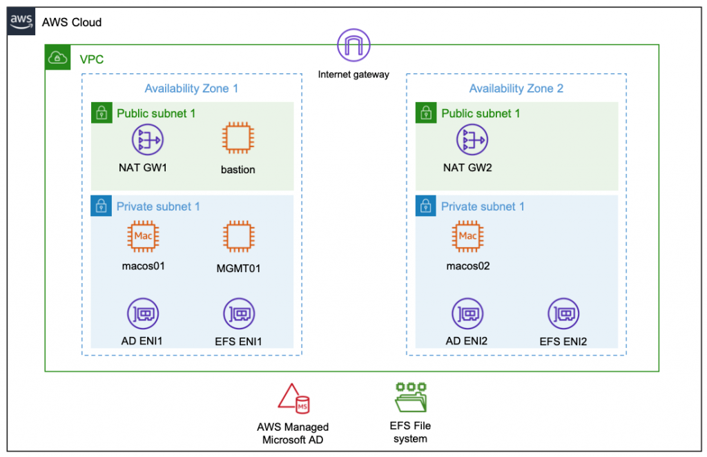
Compute Layer
The compute layer consists of two EC2 Mac instances running in isolated private subnets in different Availability Zones. In a production setup, these instances are provisioned with every necessary tool and software needed by developers to build and test their code for Apple platforms. Provisioning can be accomplished by creating custom Amazon Machine Images (AMIs) for the EC2 Mac instances or by bootstrapping them with setup scripts. This post utilizes Amazon provided AMIs with macOS BigSur without custom software. Once setup, developers gain command line access to the instances via SSH and utilize them as remote development environments.
Storage Layer
The architecture promotes the decoupling of compute and storage so that EC2 Mac instances can be updated with new OS and/or software versions without affecting the developer experience or data. Home directories reside on a highly available Amazon EFS file system, and they can be consistently accessed from all EC2 Mac instances. From a user perspective, any two EC2 Mac instances are alike, in that the user experiences the same configuration and environment (e.g., shell configurations such as .zshrc, VSCode remote extensions .vscode-server, or other tools and configurations installed within the user’s home directory). The file system is exposed to the private subnets via redundant mount target ENIs and persistently mounted on the Mac instances.
Identity Layer
For centralized user and access management, all instances in the architecture are part of a common Active Directory domain based on AWS Managed Microsoft AD. This is exposed via redundant ENIs to the private subnets containing the Mac instances.
To manage and configure the Active Directory domain, a Windows Instance (MGMT01) is deployed. For this post, we will connect to this instance for setting up Active Directory users. Note: other than that, this instance is not required for operating the solution, and it can be shut down both for reasons of cost efficiency and security.
Access Layer
The access layer constitutes the entry and exit point of the setup. For this post, it is comprised of an internet-facing bastion host connecting authorized Active Directory users to the Mac instances, as well as redundant NAT gateways providing outbound internet connectivity.
Depending on customer requirements, the access layer can be realized in various ways. For example, it can provide access to customer on-premises networks by using AWS Direct Connect or AWS Virtual Private Network (AWS VPN), or to services in different Virtual Private Cloud (VPC) networks by using AWS PrivateLink. This means that you can integrate your Mac development environment with pre-existing development-related services, such as source code and software repositories or build and test services.
Prerequisites
We utilize AWS CloudFormation to automatically deploy the entire setup in the preceding description. All templates and code can be obtained from the blog’s GitHub repository. To complete the setup, you need
An AWS Account with sufficient permissions
A computer/virtual machine with
the AWS Command Line Interface (CLI) installed and setup
a Unix Shell (e.g., bash or zsh) and git installed
an SSH client supporting the ssh_config file syntax (ideally openssh)
a Remote Desktop client
(Optional) VSCode with Remote SSH Extension installed and configured
Warning: Deploying this example will incur AWS service charges of at least $50 due to the fact that EC2 Mac instances can only be released 24 hours after allocation.
Solution Deployment
In this section, we provide a step-by-step guide for deploying the solution. We will mostly rely on AWS CLI and shell scripts provided along with the CloudFormation templates and use the AWS Management Console for checking and verification only.
1. Get the Code: Obtain the CloudFormation templates and all relevant scripts and assets via git:
git clone https://github.com/aws-samples/ec2-mac-remote-dev-env.git
cd ec2-mac-remote-dev-env
git submodule init
git submodule update
2. Create an Amazon Simple Storage Service (Amazon S3) deployment bucket and upload assets for deployment: CloudFormation templates and other assets are uploaded to this bucket in order to deploy them. To achieve this, run the upload.sh script in the repository root, accepting the default bucket configuration as suggested by the script:
./upload.sh
3. Create an SSH Keypair for admin Access: To access the instances deployed by CloudFormation, create an SSH keypair with name mac-admin, and then import it with EC2:
ssh-keygen -f ~/.ssh/mac-admin
aws ec2 import-key-pair \
--key-name "mac-admin" \
--public-key-material fileb://~/.ssh/mac-admin.pub
4. Create CloudFormation Parameters file: Initialize the json file by copying the provided template parameters-template.json :
cp parameters-template.json parameters.json
Substitute the following placeholders:
a. <YourS3BucketName>: The unique name of the S3 bucket you created in step 2.
b. <YourSecurePassword>: Active Directory domain admin password. This must be 8-32 characters long and can contain numbers, letters and symbols.
c. <YourMacOSAmiID>: We used the latest macOS BigSur AMI at the time of writing with AMI ID ami-0c84d9da210c1110b in the us-east-2 Region. You can obtain other AMI IDs for your desired AWS Region and macOS version from the console.
d. <MacHost1ID> and <MacHost2ID>: See the next step 5. on how to allocate Dedicated Hosts and obtain the host IDs.
5. Allocate Dedicated Hosts: EC2 Mac Instances run on Dedicated Hosts. Therefore, prior to being able to deploy instances, Dedicated Hosts must be allocated. We utilize us-east-2 as the target Region, and we allocate the hosts in the Availability Zones us-east-2b and us-east-2c:
aws ec2 allocate-hosts \
--auto-placement off \
--region us-east-2 \
--availability-zone us-east-2b \
--instance-type mac1.metal \
--quantity 1 \
--tag-specifications 'ResourceType=dedicated-host,Tags=[{Key=Name,Value=MacHost1}]'
aws ec2 allocate-hosts \
--auto-placement off \
--region us-east-2 \
--availability-zone us-east-2c \
--instance-type mac1.metal \
--quantity 1 \
--tag-specifications 'ResourceType=dedicated-host,Tags=[{Key=Name,Value=MacHost2}]'
Substitute the host IDs returned from those commands in the parameters.json file as instructed in the previous step 5.
6. Deploy the CloudFormation Stack: To deploy the stack with the name ec2-mac-remote-dev-env, run the provided sh script as follows:
./deploy.sh ec2-mac-remote-dev-env
Stack deployment can take up to 1.5 hours, which is due to the Microsoft Managed Active Directory, the Windows MGMT01 instance, and the Mac instances being created sequentially. Check the CloudFormation Console to see whether the stack finished deploying. In the console, under Stacks, select the stack name from the preceding code (ec2-mac-remote-dev-env), and then navigate to the Outputs Tab. Once finished, this will display the public DNS name of the bastion host, as well as the private IPs of the Mac instances. You need this information in the upcoming section in order to connect and test your setup.
Solution Test
Now you can log in and explore the setup. We will start out by creating a developer account within Active Directory and configure an SSH key in order for it to grant access.
Create an Active Directory User
Create an SSH Key for the Active Directory User and configure SSH Client
First, we create a new SSH key for the developer Active Directory user. Utilize OpenSSH CLI,
ssh-keygen -f ~/.ssh/mac-developer
Furthermore, utilizing the connection information from the CloudFormation output, setup your ~/.ssh/config to contain the following entries, where $BASTION_HOST_PUBLIC_DNS, $MAC1_PRIVATE_IP and $MAC2_PRIVATE_IP must be replaced accordingly:
Host bastion
HostName $BASTION_HOST_PUBLIC_DNS
User ec2-user
IdentityFile ~/.ssh/mac-admin
Host bastion-developer
HostName $BASTION_HOST_PUBLIC_DNS
User developer
IdentityFile ~/.ssh/mac-developer
Host macos1
HostName $MAC1_PRIVATE_IP
ProxyJump %r@bastion-developer
User developer
IdentityFile ~/.ssh/mac-developer
Host macos2
HostName $MAC2_PRIVATE_IP
ProxyJump %r@bastion-developer
User developer
IdentityFile ~/.ssh/mac-developer
As you can see from this configuration, we set up both SSH keys created during this blog. The mac-admin key that you created earlier provides access to the privileged local ec2-user account, while the mac-developer key that you just created grants access to the unprivileged AD developer account. We will create this next.
Login to the Windows MGMT Instance and setup a developer Active Directory account
Now login to the bastion host, forwarding port 3389 to the MGMT01 host in order to gain Remote Desktop Access to the Windows management instance:
ssh -L3389:mgmt01:3389 bastion
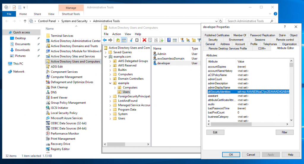
While having this connection open, launch your Remote Desktop Client and connect to localhost with Username admin and password as specified earlier in the CloudFormation parameters. Once connected to the instance, open Control Panel>System and Security>Administrative Tools and click Active Directory Users and Computers. Then, in the appearing window, enable View>Advanced Features. If you haven’t changed the Active Directory domain name explicitly in CloudFormation, then the default domain name is example.com with corresponding NetBIOS Name example. Therefore, to create a new user for that domain, select Active Directory Users and Computers>example.com>example>Users, and click Create a new User. In the resulting wizard, set the Full name and User logon name fields to developer, and proceed to set a password to create the user. Once created, right-click on the developer user, and select Properties>Attribute Editor. Search for the altSecurityIdentities property, and copy-paste the developer public SSH key (contained in ~/.ssh/mac-developer.pub) into the Value to add field, click Add, and then click OK. In the Properties window, save your changes by clicking Apply and OK. The following figure illustrates the process just described:
Connect to the EC2 Mac instances
Now that the developer account is setup, you can connect to either of the two EC2 Mac instances from your local machine with the Active Directory account:
ssh macos1
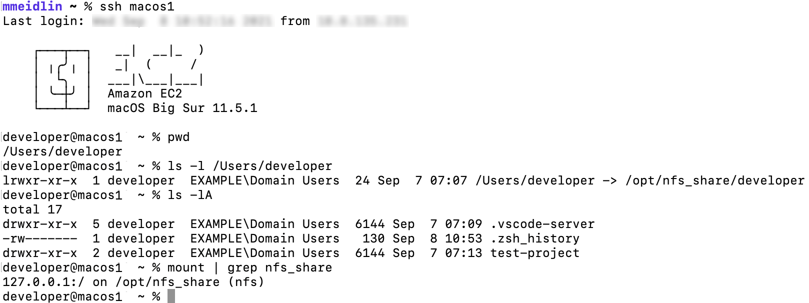
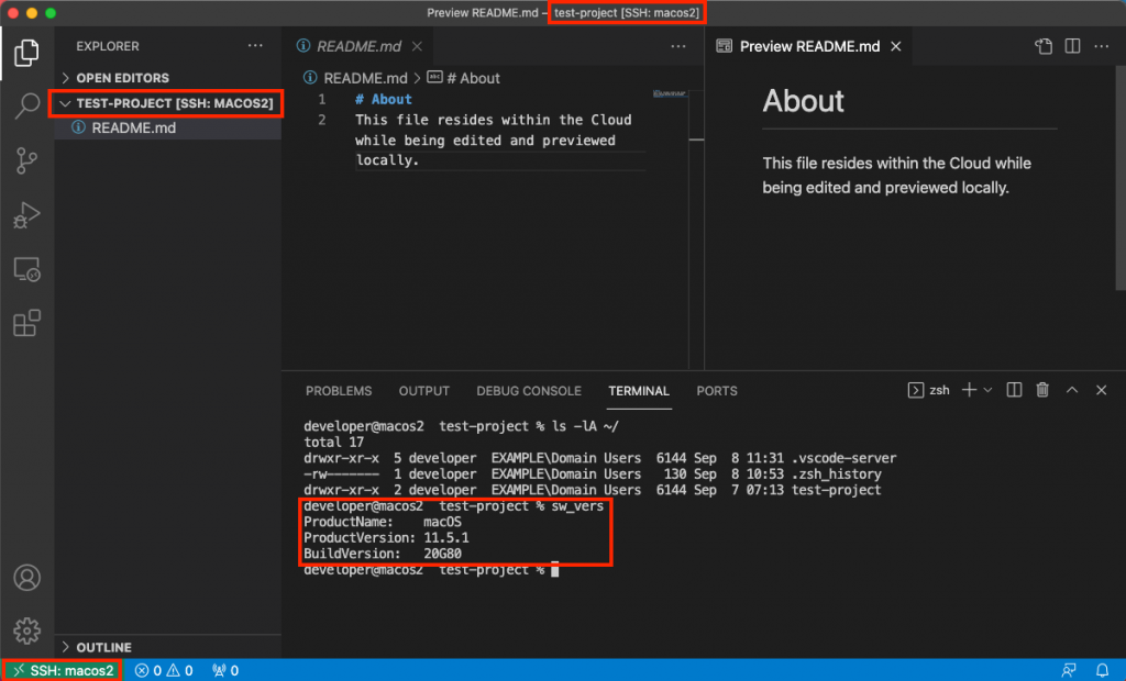
When you connect via the preceding command, your local machine first establishes an SSH connection to the bastion host which authorizes the request against the key we just stored in Active Directory. Upon success, the bastion host forwards the connection to the macos1 instance, which again authorizes against Active Directory and launches a terminal session upon success. The following figure illustrates the login with the macos1 instances, showcasing both the integration with AD (EXAMPLE\Domain Users group membership) as well as with the EFS share, which is mounted at /opt/nfsshare and symlinked to the developer’s home directory.

Likewise, you can create folders and files in the developer’s home directory such as the test-project folder depicted in the screenshot.
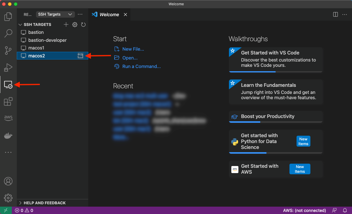
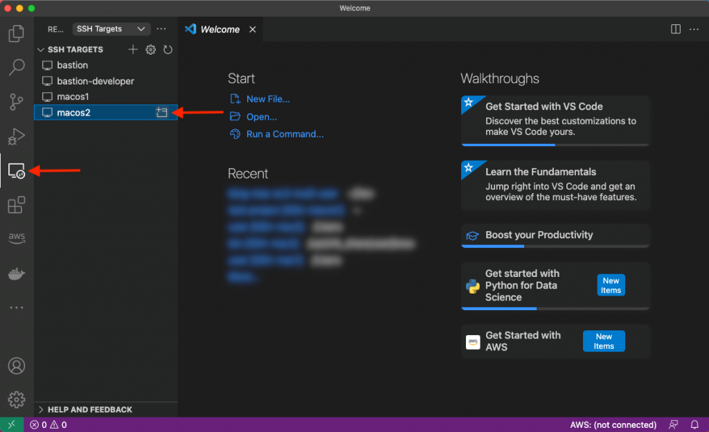
Lastly, let’s utilize VS Code’s remote plugin and connect to the other macos2 instance. Select the Remote Explorer on the left-hand pane and click to open the macos2 host as shown in the following screenshot:
A new window will be opened with the context of the remote server, as shown in the next figure. As you can see, we have access to the same files seen previously on the macos1 host.
Cleanup
From the repository root, run the provided destroy.sh script in order to destroy all resources created by CloudFormation, specifying the stack name as input parameter:
./destroy.sh ec2-mac-remote-dev-env
Check the CloudFormation Console to confirm that the stack and its resources are properly deleted.
Lastly, in the EC2 Console, release the dedicated Mac Hosts that you allocated in the beginning. Notice that this is only possible 24 hours after allocation.
Summary
This post has shown how EC2 Mac instances can be set up as remote development environments, thereby allowing developers to create software for Apple platforms regardless of their local hardware and software setup. Aside from increased flexibility and maintainability, this setup also saves cost because multiple developers can work interactively with the same EC2 Mac instance. We have rolled out an architecture that integrates EC2 Mac instances with AWS Directory Services for centralized user and access management as well as Amazon EFS to store developer home directories in a durable and highly available manner. This has resulted in an architecture where instances can easily be added, removed, or updated without affecting developer workflow. Now, irrespective of your client machine, you are all set to start coding with your local editor while leveraging EC2 Mac instances in the AWS Cloud to provide you with a macOS environment! To get started and learn more about EC2 Mac instances, please visit the product page.
Publishing messages in batch to Amazon SNS topics
=======================
This post is written by Heeki Park (Principal Solutions Architect, Serverless Specialist), Marc Pinaud (Senior Product Manager, Amazon SNS), Amir Eldesoky (Software Development Engineer, Amazon SNS), Jack Li (Software Development Engineer, Amazon SNS), and William Nguyen (Software Development Engineer, Amazon SNS).
Today, we are announcing the ability for AWS customers to publish messages in batch to Amazon SNS topics. Until now, you were only able to publish one message to an SNS topic per Publish API request. With the new PublishBatch API, you can send up to 10 messages at a time in a single API request. This reduces cost for API requests by up to 90%, as you need fewer API requests to publish the same number of messages.
Introducing the PublishBatch API
Consider a log processing application where you process system logs and have different requirements for downstream processing. For example, you may want to do inference on incoming log data, populate an operational Amazon OpenSearch Service environment, and store log data in an enterprise data lake.

Systems send log data to a standard SNS topic, and Amazon SQS queues and Amazon Kinesis Data Firehose are configured as subscribers. An AWS Lambda function subscribes to the first SQS queue and uses machine learning models to perform inference to detect security incidents or system access anomalies. A Lambda function subscribes to the second SQS queue and emits those log entries to an Amazon OpenSearch Service cluster. The workload uses Kibana dashboards to visualize log data. An Amazon Kinesis Data Firehose delivery stream subscribes to the SNS topic and archives all log data into Amazon S3. This allows data scientists to conduct further investigation and research on those logs.
To do this, the following Java code publishes a set of log messages. In this code, you construct a publish request for a single message to an SNS topic and submit that request via the publish() method:
SNS Standard Publish Request
private static AmazonSNS snsClient;
private static final String MESSAGE_PAYLOAD = " 192.168.1.100 - - [28/Oct/2021:10:27:10 -0500] "GET /index.html HTTP/1.1" 200 3395";
PublishRequest request = new PublishRequest()
.withTopicArn(topicArn)
.withMessage(MESSAGE_PAYLOAD);
PublishResult response = snsClient.publish(request);
SNS FIFO Publish Request
private static AmazonSNS snsClient;
private static final String MESSAGE_PAYLOAD = " 192.168.1.100 - - [28/Oct/2021:10:27:10 -0500] "GET /index.html HTTP/1.1" 200 3395";
private static final String MESSAGE_FIFO_GROUP = "server1234";
PublishRequest request = new PublishRequest()
.withTopicArn(topicArn)
.withMessage(MESSAGE_PAYLOAD)
.withMessageGroupId(MESSAGE_FIFO_GROUP)
.withMessageDeduplicationId(UUID.randomUUID().toString());
PublishResult response = snsClient.publish(request);
If you extended the example above and had 10 log lines that each needed to be published as a message, you would have to write code to construct 10 publish requests, and subsequently submit each of those requests via the publish() method.
With the new ability to publish batch messages, you write the following new code. In the code below, you construct a list of publish entries first, then create a single publish batch request, and subsequently submit that batch request via the new publishBatch() method. In the code below, you use a sample helper method getLoggingPayload(i) to get the appropriate payload for the message, which you can replace with your own business logic.
SNS Standard PublishBatch Request
private static final String MESSAGE_BATCH_ID_PREFIX = "server1234-batch-id-";
List<PublishBatchRequestEntry> entries = IntStream.range(0, 10)
.mapToObj(i -> {
new PublishBatchRequestEntry()
.withId(MESSAGE_BATCH_ID_PREFIX + i)
.withMessage(getLoggingPayload(i));
})
.collect(Collectors.toList());
PublishBatchRequest request = new PublishBatchRequest()
.withTopicArn(topicArn)
.withPublishBatchRequestEntries(entries);
PublishBatchResult response = snsClient.publishBatch(request);
SNS FIFO PublishBatch Request
List<PublishBatchRequestEntry> entries = IntStream.range(0, 10)
.mapToObj(i -> {
new PublishBatchRequestEntry()
.withId(MESSAGE_BATCH_ID_PREFIX + i)
.withMessage(getLoggingPayload(i))
.withMessageGroupId(MESSAGE_FIFO_GROUP)
.withMessageDeduplicationId(UUID.randomUUID().toString());
})
.collect(Collectors.toList());
PublishBatchRequest request = new PublishBatchRequest()
.withTopicArn(topicArn)
.withPublishBatchRequestEntries(entries);
PublishBatchResult response = snsClient.publishBatch(request);
In the list of publish entries, the application must assign a unique batch ID (up to 80 characters) to each publish entry within that batch. When the SNS service successfully receives a message, the SNS service assigns a unique message ID and returns that message ID in the response object.
If publishing to a FIFO topic, the SNS service additionally returns a sequence number in the response. When publishing a batch of messages, the PublishBatchResult object returns a list of response objects for successful and failed messages. If you iterate through the list of response objects for successful messages, you might see the following:
SNS Standard PublishBatch Response
{
"Id": "server1234-batch-id-0",
"MessageId": "fcaef5b3-e9e3-5c9e-b761-ac46c4a779bb",
...
}
SNS FIFO PublishBatch Response
{
"Id": "server1234-batch-id-0",
"MessageId": "fcaef5b3-e9e3-5c9e-b761-ac46c4a779bb",
"SequenceNumber": "10000000000000003000",
...
}
When receiving the message from SNS in the SQS queue, the application reads the following message:
SQS Standard ReceiveMessage Response
{
"Type" : "Notification",
"MessageId" : "fcaef5b3-e9e3-5c9e-b761-ac46c4a779bb",
"TopicArn" : "arn:aws:sns:us-east-1:112233445566:publishBatchTopic",
"Message" : "payload-0",
"Timestamp" : "2021-10-28T22:58:12.862Z",
"UnsubscribeURL" : "http://sns.us-east-1.amazon.com/?Action=Unsubscribe&SubscriptionArn=arn:aws:sns:us-east-1:112233445566:publishBatchTopic:ff78260a-0953-4b60-9c2c-122ebcb5fc96"
}
SQS FIFO ReceiveMessage Response
{
"Type" : "Notification",
"MessageId" : "fcaef5b3-e9e3-5c9e-b761-ac46c4a779bb",
"SequenceNumber" : "10000000000000003000",
"TopicArn" : "arn:aws:sns:us-east-1:112233445566:publishBatchTopic",
"Message" : "payload-0",
"Timestamp" : "2021-10-28T22:58:12.862Z",
"UnsubscribeURL" : "http://sns.us-east-1.amazon.com/?Action=Unsubscribe&SubscriptionArn=arn:aws:sns:us-east-1:112233445566:publishBatchTopic.fifo:ff78260a-0953-4b60-9c2c-122ebcb5fc96"
}
In the standard publish example, the MessageId of fcaef5b3-e9e3-5c9e-b761-ac46c4a779bb is propagated down to the message in SQS. In the FIFO publish example, the SequenceNumber of 10000000000000003000 is also propagated down to the message in SQS.
Handling errors and quotas
When publishing messages in batch, the application must handle errors that may have occurred during the publish batch request. Errors can occur at two different levels. The first is when publishing the batch request to the SNS topic. For example, if the application does not specify a unique message batch ID, it fails with the following error:
com.amazonaws.services.sns.model.BatchEntryIdsNotDistinctException: Two or more batch entries in the request have the same Id. (Service: AmazonSNS;Status Code: 400; Error Code: BatchEntryIdsNotDistinct; Request ID: 44cdac03-eeac-5760-9264-f5f99f4914ad; Proxy: null)
The second is within the batch request at the message level. The application must inspect the returned PublishBatchResult object by iterating through successful and failed responses:
PublishBatchResult publishBatchResult = snsClient.publishBatch(request);
publishBatchResult.getSuccessful().forEach(entry -> {
System.out.println(entry.toString());
});
publishBatchResult.getFailed().forEach(entry -> {
System.out.println(entry.toString());
});
With respect to quotas, the overall message throughput for an SNS topic remains the same. For example, in US East (N. Virginia), standard topics support up to 30,000 messages per second. Before this feature, 30,000 messages also meant 30,000 API requests per second. Because SNS now supports up to 10 messages per request, you can publish the same number of messages using only 3,000 API requests. With FIFO topics, the message throughput remains the same at 300 messages per second, but you can now send that volume of messages using only 30 API requests, thus reducing your messaging costs with SNS.
Conclusion
SNS now supports the ability to publish up to 10 messages in a single API request, reducing costs for publishing messages into SNS. Your applications can validate the publish status of each of the messages sent in the batch and handle failed publish requests accordingly. Message throughput to SNS topics remains the same for both standard and FIFO topics.
Learn more about this ability in the SNS Developer Guide.
Learn more about the details of the API request in the SNS API reference.
Learn more about SNS quotas.
For more serverless learning resources, visit Serverless Land.
Deploying AWS Lambda layers automatically across multiple Regions
=======================
This post is written by Ben Freiberg, Solutions Architect, and Markus Ziller, Solutions Architect.
Many developers import libraries and dependencies into their AWS Lambda functions. These dependencies can be zipped and uploaded as part of the build and deployment process but it’s often easier to use Lambda layers instead.
A Lambda layer is an archive containing additional code, such as libraries or dependencies. Layers are deployed as immutable versions, and the version number increments each time you publish a new layer. When you include a layer in a function, you specify the layer version you want to use.
Lambda layers simplify and speed up the development process by providing common dependencies and reducing the deployment size of your Lambda functions. To learn more, refer to Using Lambda layers to simplify your development process.
Many customers build Lambda layers for use across multiple Regions. But maintaining up-to-date and consistent layer versions across multiple Regions is a manual process. Layers are set as private automatically but they can be shared with other AWS accounts or shared publicly. Permissions only apply to a single version of a layer. This solution automates the creation and deployment of Lambda layers across multiple Regions from a centralized pipeline.
Overview of the solution
This solution uses AWS Lambda, AWS CodeCommit, AWS CodeBuild and AWS CodePipeline.
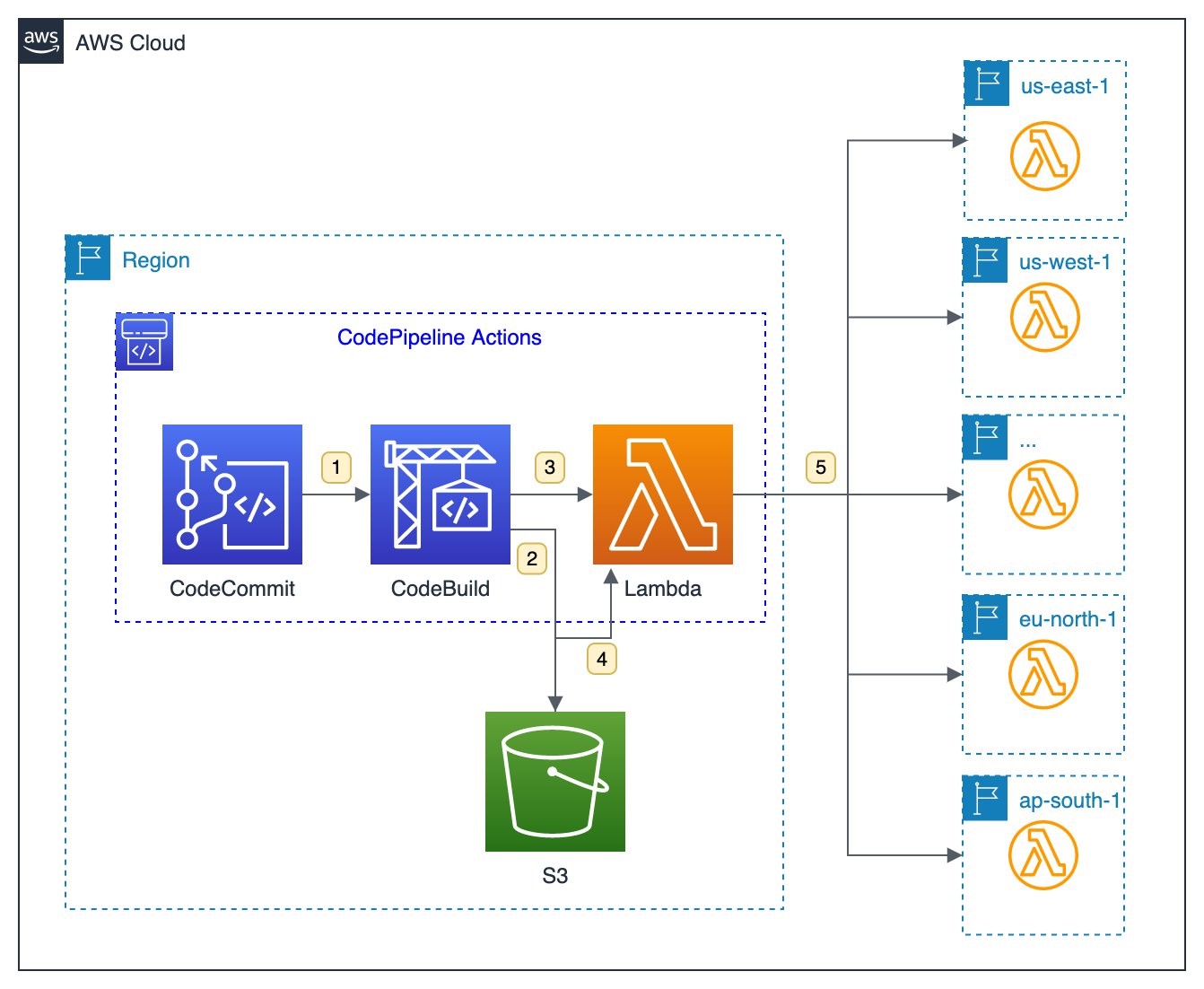
This diagram outlines the workflow implemented in this blog:
- A CodeCommit repository contains the language-specific definition of dependencies and libraries that the layer contains, such as package.json for Node.js or requirements.txt for Python. Each commit to the main branch triggers an execution of the surrounding CodePipeline.
- A CodeBuild job uses the provided buildspec.yaml to create a zipped archive containing the layer contents. CodePipeline automatically stores the output of the CodeBuild job as artifacts in a dedicated Amazon S3 bucket.
- A Lambda function is invoked for each configured Region.
- The function first downloads the zip archive from S3.
- Next, the function creates the layer version in the specified Region with the configured permissions.
Walkthrough
The following walkthrough explains the components and how the provisioning can be automated via CDK. For this walkthrough, you need:
An AWS account.
Installed and authenticated AWS CLI (authenticate with an IAM user or an AWS STS security token).
Installed Node.js, TypeScript.
Installed git.
AWS CDK installed.
To deploy the sample stack:
- Clone the associated GitHub repository by running the following command in a local directory:
git clone https://github.com/aws-samples/multi-region-lambda-layers
- Open the repository in your preferred editor and review the contents of the src and cdk folder.
- Follow the instructions in the README.md to deploy the stack.
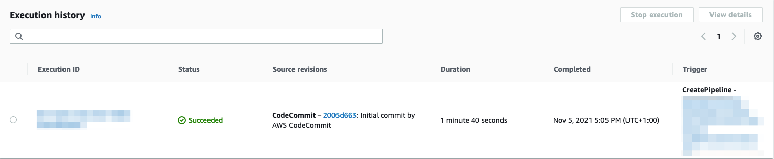
- Check the execution history of your pipeline in the AWS Management Console. The pipeline has been started once already and published a first version of the Lambda layer.

Code repository
The source code of the Lambda layers is stored in AWS CodeCommit. This is a secure, highly scalable, managed source control service that hosts private Git repositories. This example initializes a new repository as part of the CDK stack:
    const asset = new Asset(this, 'SampleAsset', {
path: path.join(__dirname, '../../res')
});
const cfnRepository = new codecommit.CfnRepository(this, 'lambda-layer-source', {
repositoryName: 'lambda-layer-source',
repositoryDescription: 'Contains the source code for a nodejs12+14 Lambda layer.',
code: {
branchName: 'main',
s3: {
bucket: asset.s3BucketName,
key: asset.s3ObjectKey
}
},
});
This code uploads the contents of the ./cdk/res/ folder to an S3 bucket that is managed by the CDK. The CDK then initializes a new CodeCommit repository with the contents of the bucket. In this case, the repository gets initialized with the following files:
LICENSE: A text file describing the license for this Lambda layer
package.json: In Node.js, the package.json file is a manifest for projects. It defines dependencies, scripts, and metainformation about the project. The npm install command installs all project dependencies in a node_modules folder. This is where you define the contents of the Lambda layer.
The default package.json in the sample code defines a Lambda layer with the latest version of the AWS SDK for JavaScript:
{
"name": "lambda-layer",
"version": "1.0.0",
"description": "Sample AWS Lambda layer",
"dependencies": {
"aws-sdk": "latest"
}
}
To see what is included in the layer, run npm install in the ./cdk/res/ directory. This shows the files that are bundled into the Lambda layer. The contents of this folder initialize the CodeCommit repository, so delete node_modules and package-lock.json inspecting these files.

This blog post uses a new CodeCommit repository as the source but you can adapt this to other providers. CodePipeline also supports repositories on GitHub and Bitbucket. To connect to those providers, see the documentation.
CI/CD Pipeline
CodePipeline automates the process of building and distributing Lambda layers across Region for every change to the main branch of the source repository. It is a fully managed continuous delivery service that helps you automate your release pipelines for fast and reliable application and infrastructure updates. CodePipeline automates the build, test, and deploy phases of your release process every time there is a code change, based on the release model you define.
The CDK creates a pipeline in CodePipeline and configures it so that every change to the code base of the Lambda layer runs through the following three stages:
new codepipeline.Pipeline(this, 'Pipeline', {
pipelineName: 'LambdaLayerBuilderPipeline',
stages: [
{
stageName: 'Source',
actions: [sourceAction]
},
{
stageName: 'Build',
actions: [buildAction]
},
{
stageName: 'Distribute',
actions: parallel,
}
]
});
Source
The source phase is the first phase of every run of the pipeline. It is typically triggered by a new commit to the main branch of the source repository. You can also start the source phase manually with the following AWS CLI command:
aws codepipeline start-pipeline-execution --name LambdaLayerBuilderPipeline
When started manually, the current head of the main branch is used. Otherwise CodePipeline checks out the code in the revision of the commit that triggered the pipeline execution.
CodePipeline stores the code locally and uses it as an output artifact of the Source stage. Stages use input and output artifacts that are stored in the Amazon S3 artifact bucket you chose when you created the pipeline. CodePipeline zips and transfers the files for input or output artifacts as appropriate for the action type in the stage.
Build
In the second phase of the pipeline, CodePipeline installs all dependencies and packages according to the specs of the targeted Lambda runtime. CodeBuild is a fully managed build service in the cloud. It reduces the need to provision, manage, and scale your own build servers. It provides prepackaged build environments for popular programming languages and build tools like npm for Node.js.
In CodeBuild, you use build specifications (buildspecs) to define what commands need to run to build your application. Here, it runs commands in a provisioned Docker image with Amazon Linux 2 to do the following:
Create the folder structure expected by Lambda Layer.
Run npm install to install all Node.js dependencies.
Package the code into a layer.zip file and define layer.zip as output of the Build stage.
The following CDK code highlights the specifications of the CodeBuild project.
const buildAction = new codebuild.PipelineProject(this, 'lambda-layer-builder', {
buildSpec: codebuild.BuildSpec.fromObject({
version: '0.2',
phases: {
install: {
commands: [
'mkdir -p node_layer/nodejs',
'cp package.json ./node_layer/nodejs/package.json',
'cd ./node_layer/nodejs',
'npm install',
]
},
build: {
commands: [
'rm package-lock.json',
'cd ..',
'zip ../layer.zip * -r',
]
}
},
artifacts: {
files: [
'layer.zip',
]
}
}),
environment: {
buildImage: codebuild.LinuxBuildImage.STANDARD_5_0
}
})
Distribute
In the final stage, Lambda uses layer.zip to create and publish a Lambda layer across multiple Regions. The sample code defines four Regions as targets for the distribution process:
regionCodesToDistribute: ['eu-central-1', 'eu-west-1', 'us-west-1', 'us-east-1']
The Distribution phase consists of n (one per Region) parallel invocations of the same Lambda function, each with userParameter.region set to the respective Region. This is defined in the CDK stack:
const parallel = props.regionCodesToDistribute.map((region) => new codepipelineActions.LambdaInvokeAction({
actionName: `distribute-${region}`,
lambda: distributor,
inputs: [buildOutput],
userParameters: { region, layerPrincipal: props.layerPrincipal }
}));
Each Lambda function runs the following code to publish a new Lambda layer in each Region:
// Simplified code for brevity
// Omitted error handling, permission management and logging
// See code samples for full code.
export async function handler(event: any) {
// #1 Get job specific parameters (e.g. target region)
const { location } = event['CodePipeline.job'].data.inputArtifacts[0];
const { region, layerPrincipal } = JSON.parse(event["CodePipeline.job"].data.actionConfiguration.configuration.UserParameters);
// #2 Get location of layer.zip and download it locally
const layerZip = s3.getObject(/* Input artifact location*/);
const lambda = new Lambda({ region });
// #3 Publish a new Lambda layer version based on layer.zip
const layer = lambda.publishLayerVersion({
Content: {
ZipFile: layerZip.Body
},
LayerName: 'sample-layer',
CompatibleRuntimes: ['nodejs12.x', 'nodejs14.x']
})
// #4 Report the status of the operation back to CodePipeline
return codepipeline.putJobSuccessResult(..);
}
After each Lambda function completes successfully, the pipeline ends. In a production application, you likely would have additional steps after publishing. For example, it may send notifications via Amazon SNS. To learn more about other possible integrations, read Working with pipeline in CodePipeline.

Testing the workflow
With this automation, you can release a new version of the Lambda layer by changing package.json in the source repository.
Add the AWS X-Ray SDK for Node.js as a dependency to your project, by making the following changes to package.json and committing the new version to your main branch:
{
"name": "lambda-layer",
"version": "1.0.0",
"description": "Sample AWS Lambda layer",
"dependencies": {
"aws-sdk": "latest",
"aws-xray-sdk": "latest"
}
}
After committing the new version to the repository, the pipeline is triggered again. After a while, you see that an updated version of the Lambda layer is published to all Regions:

Cleaning up
Many services in this blog post are available in the AWS Free Tier. However, using this solution may incur cost and you should tear down the stack if you don’t need it anymore. Cleaning up steps are included in the readme in the repository.
Conclusion
This blog post shows how to create a centralized pipeline to build and distribute Lambda layers consistently across multiple Regions. The pipeline is configurable and allows you to adapt the Regions and permissions according to your use-case.
For more serverless learning resources, visit Serverless Land.
Modernizing deployments with container images in AWS Lambda
=======================
This post is written by Joseph Keating, AWS Modernization Architect, and Virginia Chu, Sr. DevSecOps Architect.
Container image support for AWS Lambda enables developers to package function code and dependencies using familiar patterns and tools. With this pattern, developers use standard tools like Docker to package their functions as container images and deploy them to Lambda.
In a typical deployment process for image-based Lambda functions, the container and Lambda function are created or updated in the same process. However, some use cases require developers to create the image first, and then update one or more Lambda functions from that image. In these situations, organizations may mandate that infrastructure components such as Amazon S3 and Amazon Elastic Container Registry (ECR) are centralized and deployed separately from their application deployment pipelines.
This post demonstrates how to use AWS continuous integration and deployment (CI/CD) services and Docker to separate the container build process from the application deployment process.
Overview
There is a sample application that creates two pipelines to deploy a Java application. The first pipeline uses Docker to build and deploy the container image to the Amazon ECR. The second pipeline uses AWS Serverless Application Model (AWS SAM) to deploy a Lambda function based on the container from the first process.
This shows how to build, manage, and deploy Lambda container images automatically with infrastructure as code (IaC). It also covers automatically updating or creating Lambda functions based on a container image version.

Example architecture
The example application uses AWS CloudFormation to configure the AWS Lambda container pipelines. Both pipelines use AWS CodePipeline, AWS CodeBuild, and AWS CodeCommit. The lambda-container-image-deployment-pipeline builds and deploys a container image to ECR. The sam-deployment-pipeline updates or deploys a Lambda function based on the new container image.
The pipeline deploys the sample application:
- The developer pushes code to the main branch.
- An update to the main branch invokes the pipeline.
- The pipeline clones the CodeCommit repository.
- Docker builds the container image and assigns tags.
- Docker pushes the image to ECR.
- The lambda-container-image-pipeline completion triggers an Amazon EventBridge event.
- The pipeline clones the CodeCommit repository.
- AWS SAM builds the Lambda-based container image application.
- AWS SAM deploys the application to AWS Lambda.
Prerequisites
To provision the pipeline deployment, you must have the following prerequisites:
A Git client to clone the source code in a repository.
An IAM user with Git credentials.
An AWS account with local credentials properly configured (typically under ~/.aws/credentials).
The latest version of the AWS CLI. For more information, see installing, updating, and uninstalling the AWS CLI.
Infrastructure configuration
The pipeline relies on infrastructure elements like AWS Identity and Access Management roles, S3 buckets, and an ECR repository. Due to security and governance considerations, many organizations prefer to keep these infrastructure components separate from their application deployments.
To start, deploy the core infrastructure components using CloudFormation and the AWS CLI:
- Create a local directory called BlogDemoRepo and clone the source code repository found in the following location:
mkdir -p $HOME/BlogDemoRepo
cd $HOME/BlogDemoRepo
git clone https://github.com/aws-samples/modernize-deployments-with-container-images-in-lambda
- Change directory into the cloned repository:
cd modernize-deployments-with-container-images-in-lambda/
- Deploy the s3-iam-config CloudFormation template, keeping the following CloudFormation template names:
aws cloudformation create-stack \
--stack-name s3-iam-config \
--template-body file://templates/s3-iam-config.yml \
--parameters file://parameters/s3-iam-config-params.json \
--capabilities CAPABILITY_NAMED_IAM
The output should look like the following:

Output example for stack creation
Application overview
The application uses Docker to build the container image and an ECR repository to store the container image. AWS SAM deploys the Lambda function based on the new container.
The example application in this post uses a Java-based container image using Amazon Corretto. Amazon Corretto is a no-cost, multi-platform, production-ready Open Java Development Kit (OpenJDK).
The Lambda container-image base includes the Amazon Linux operating system, and a set of base dependencies. The image also consists of the Lambda Runtime Interface Client (RIC) that allows your runtime to send and receive to the Lambda service. Take some time to review the Dockerfile and how it configures the Java application.
Configure the repository
The CodeCommit repository contains all of the configurations the pipelines use to deploy the application. To configure the CodeCommit repository:
- Get metadata about the CodeCommit repository created in a previous step. Run the following command from the BlogDemoRepo directory created in a previous step:
aws codecommit get-repository \
--repository-name DemoRepo \
--query repositoryMetadata.cloneUrlHttp \
--output text
The output should look like the following:

Output example for get repository
- In your terminal, paste the Git URL from the previous step and clone the repository:
git clone <insert_url_from_step_1_output> You receive a warning because the repository is empty.

Empty repository warning
- Create the main branch:
cd DemoRepo
git checkout -b main
- Copy all of the code from the cloned GitHub repository to the CodeCommit repository:
cp -r ../modernize-deployments-with-container-images-in-lambda/* .
- Commit and push the changes:
git add .
git commit -m "Initial commit"
git push -u origin main
Pipeline configuration
This example deploys two separate pipelines. The first is called the modernize-deployments-with-container-images-in-lambda, which consists of building and deploying a container-image to ECR using Docker and the AWS CLI. An EventBridge event starts the pipeline when the CodeCommit branch is updated.
The second pipeline, sam-deployment-pipeline, is where the container image built from lambda-container-image-deployment-pipeline is deployed to a Lambda function using AWS SAM. This pipeline is also triggered using an Amazon EventBridge event. Successful completion of the lambda-container-image-deployment-pipeline invokes this second pipeline through Amazon EventBridge.
Both pipelines consist of AWS CodeBuild jobs configured with a buildspec file. The buildspec file enables developers to run bash commands and scripts to build and deploy applications.
Deploy the pipeline
You now configure and deploy the pipelines and test the configured application in the AWS Management Console.
- Change directory back to modernize-serverless-deployments-leveraging-lambda-container-images directory and deploy the lambda-container-pipeline CloudFormation Template:
cd $HOME/BlogDemoRepo/modernize-deployments-with-container-images-in-lambda/
aws cloudformation create-stack \
--stack-name lambda-container-pipeline \
--template-body file://templates/lambda-container-pipeline.yml \
--parameters file://parameters/lambda-container-params.json  \
--capabilities CAPABILITY_IAM \
--region us-east-1
The output appears:

Output example for stack creation
- Wait for the lambda-container-pipeline stack from the previous step to complete and deploy the sam-deployment-pipeline CloudFormation template:
aws cloudformation create-stack \
--stack-name sam-deployment-pipeline \
--template-body file://templates/sam-deployment-pipeline.yml \
--parameters file://parameters/sam-deployment-params.json  \
--capabilities CAPABILITY_IAM \
--region us-east-1
The output appears:

Output example of stack creation
- In the console, select CodePipeline → pipelines:

- Wait for the status of both pipelines to show Succeeded:

- Navigate to the ECR console and choose demo-java. This shows that the pipeline is built and the image is deployed to ECR.
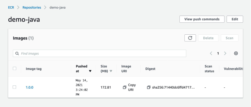
- Navigate to the Lambda console and choose the MyCustomLambdaContainer function.
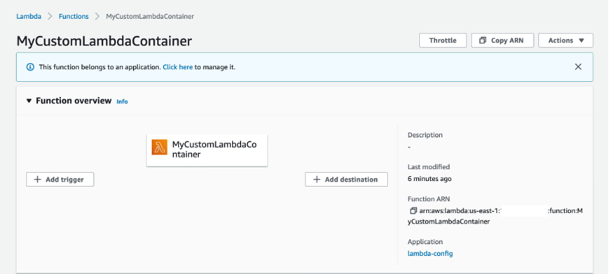
- The Image configuration panel shows that the function is configured to use the image created earlier.

- To test the function, choose Test.

- Keep the default settings and choose Test.
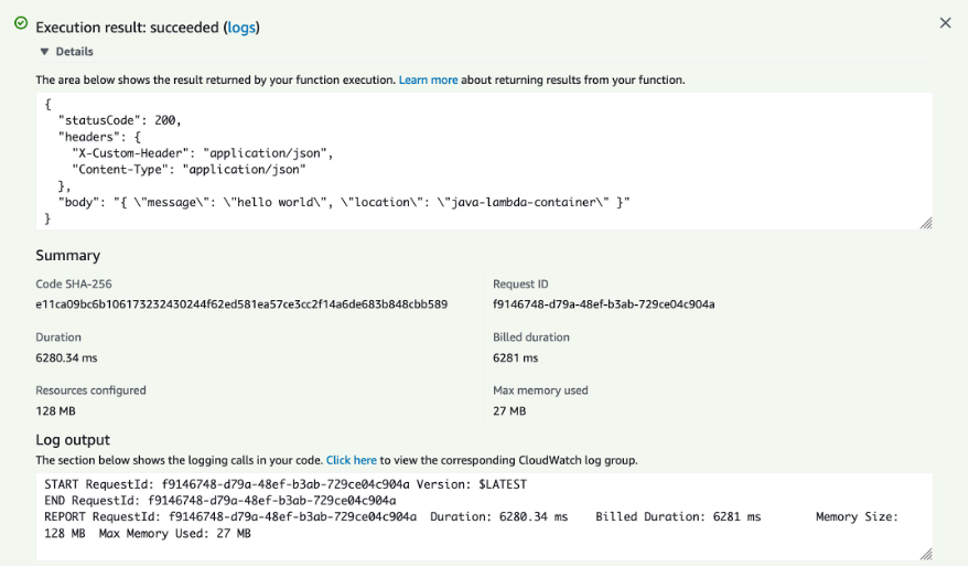
This completes the walkthrough. To further test the workflow, modify the Java application and commit and push your changes to the main branch. You can then review the updated resources you have deployed.
Conclusion
This post shows how to use AWS services to automate the creation of Lambda container images. Using CodePipeline, you create a CI/CD pipeline for updates and deployments of Lambda container-images. You then test the Lambda container-image in the AWS Management Console.
For more serverless content visit Serverless Land.
Monitoring delay of AWS Batch jobs in transit before execution
=======================
This post is written by Nikhil Anand, Solutions Architect
AWS Batch enables developers, scientists, and engineers to easily and efficiently run hundreds of thousands of batch processing jobs on AWS. With AWS Batch you no longer have to install and manage batch computing software or server clusters used to run your jobs. This lets you focus on analyzing results and solving problems, not managing infrastructure. When you use AWS Batch, in the job lifetime, a job goes through several states. When creating a compute environment to run the Batch jobs and submit Batch jobs, a settings misconfiguration could cause the job to get stuck in a transit state. This means the job will not proceed to the desired RUNNING state – a common issue faced by most customers.
If your compute environment contains compute resources, but your jobs don’t progress beyond the RUNNABLE state, then something is preventing the jobs from being placed on a compute resource. There are various reasons why a job could remain in the RUNNABLE state. The usual call to action is referring the troubleshooting documentation in order to fix the issue. Similarly, if your job is dependent on another job, then the job would stay in the PENDING state.
However, if you have scheduled actions to be completed with Batch jobs, or if you do not have any mechanism monitoring the jobs, then your jobs might stay in any of the transit states if left unattended. You may end up continuing forward, unaware that your job has yet to run. Eventually, when you see the jobs not progressing beyond the RUNNABLE or PENDING state, you miss the task that the job was expected to do in the given timeframe. This can result in additional time and effort troubleshooting the stuck job.
To prevent this accidental avoidance or lack of in-transit job monitoring, this post provides a monitoring solution for jobs in transit (from the SUBMITTED to the RUNNING state) in AWS Batch.
You can configure a threshold monitoring duration for your jobs so that if a job stays in SUBMITTED/PENDING/RUNNABLE longer than that, then you get a notification. For example, you might have a job that you would want to proceed to the RUNNING state in approximately 15 minutes since the job submission. Sometimes a slight misconfiguration can cause the job to get stuck in RUNNABLE indefinitely. In that case, you can set a threshold of 15 minutes. Or, suppose you have a job that is dependent on the other job that is stuck in processing. In these situations, once the specified duration is crossed, you are notified about your job staying in transit beyond your defined threshold status.
The solution is deployed by using AWS CloudFormation.
Overview of solution
The solution creates an Amazon CloudWatch Events rule that triggers an AWS Lambda function on a schedule. Then, the Lambda function checks every job in transit for more than ‘X’ seconds on all compute environments since the job submission. Specify your own value for ‘X’ when you launch the AWS CloudFormation stack. The solution consists of the following components created via CloudFormation:
An Amazon CloudWatch event rule to monitor the submitted jobs in Batch using the target Lambda function
An AWS Lambda function with the logic to monitor the submitted jobs and trigger Amazon Simple Notification Service (Amazon SNS) notifications
A Lambda execution AWS Identity and Access Management (IAM) role
An Amazon SNS topic to be subscribed by end users in order to be notified about the submitted jobs

Prerequisites
For this walkthrough, you should have the following prerequisites:
An AWS account
An AWS Identity and Access Management (IAM) user authorized to use the AWS resources
IAM roles for your AWS Batch compute environments and container instances
AWS Batch resources – compute environment, job queue, and job definition
AWS Batch jobs that would be monitored using this solution.
Walkthrough
To provision the necessary solution components, use this CloudFormation template.
- While launching the CloudFormation stack, you will be asked to input the following information in addition to the CloudFormation stack name:
- The upper threshold (in seconds) for the jobs to stay in the transit state
- The evaluation period after which the Lambda runs periodically
- The email ID to get notifications after the job stays in the transit state for the defined threshold value.
- Once the stack is created, the following resources will be provisioned – SNS topic, CloudWatch Events rule, Lambda function, Lambda invoke permissions, and Lambda execution role. View it in the ‘Resources’ tab of your CloudFormation stack.

- After the stack is created, the email ID you entered in step III above will receive an email from Amazon SNS in order to confirm the Amazon SNS subscription.

Click Confirm subscription in the email.

- Based on the customer’s inputs during stack launch, a Lambda function will be periodically invoked to look out for Batch jobs stuck in the RUNNABLE state for the defined threshold.
- An Amazon SNS notification is sent out at the evaluation periods with the job IDs of the jobs that have stayed stuck in the RUNNABLE state.
Verifying the solution
Launch your monitoring solution by using the CloudFormation template. Once the stack creation is complete, I get an email to subscribe to the SNS topic. Then, I subscribe to the SNS topic.
Click to launch Stack.
Submit a job in AWS Batch by using console, CLI, or SDK. To test the solution, submit a job, Job1, to a job queue associated with a compute environment with no public subnets. Compute resources require access in order to communicate with the Amazon ECS service endpoint. This can be done through an interface VPC endpoint or your compute resources having public IP addresses. Since the compute environment was configured to only have a private subnet, Job1 will not proceed from the RUNNABLE state. Similarly, submit another job, Job2, and during submission add a dependency of Job1 on Job2. Therefore, Job2 will not proceed from the PENDING state. Thus, creating a sample space wherein two jobs will be stuck in transit.

Based on the CloudFormation template inputs, you will get notified on the subscribed Email ID when the job stays in transit for more than ‘X’ seconds (the input provided during stack launch).

Modifications
The Lambda function uses the ListJobs API call. The maximum number of results is returned by ListJobs in paginated output. Therefore, if you are submitting many jobs, then you must modify the Lambda function to fetch more results from the initial response of the call by using the nextToken response element. Use this nextToken element and iterate through in a loop to keep fetching the paginated results until there are no further nextToken elements present.
Cleaning up
To avoid incurring future charges, delete the resources. You can delete the CloudFormation stack that will clean up every resource that it provisioned for the monitoring solution.
Conclusion
This solution lets you detect AWS Batch jobs that remain in the transit state longer than expected. It provides you with an efficient way to monitor your Batch jobs. If the jobs stay in the RUNNABLE/PENDING/SUBMITTED state for a significant amount of time, then it is indicative of potential misconfiguration with either the compute environment setup, or with the job parameters that were passed during the job submission. An early notification around the issue can help you troubleshoot the misconfigurations early on and take subsequent actions.
If you have multiple jobs that remain in the RUNNABLE state and you realize that they will not proceed further to the RUNNING state due to a misconfiguration, then you can shut down all RUNNABLE jobs by using a simple bash script.
For additional references regarding troubleshooting RUNNABLE jobs in AWS Batch, refer to the suggested Knowledge Center article and the troubleshooting documentation.
Optimizing Apache Flink on Amazon EKS using Amazon EC2 Spot Instances
=======================
This post is written by Kinnar Sen, Senior EC2 Spot Specialist Solutions Architect
Apache Flink is a distributed data processing engine for stateful computations for both batch and stream data sources. Flink supports event time semantics for out-of-order events, exactly-once semantics, backpressure control, and optimized APIs. Flink has connectors for third-party data sources and AWS Services, such as Apache Kafka, Apache NiFi, Amazon Kinesis, and Amazon MSK. Flink can be used for Event Driven (Fraud Detection), Data Analytics (Ad-Hoc Analysis), and Data Pipeline (Continuous ETL) applications. Amazon Elastic Kubernetes Service (Amazon EKS) is the chosen deployment option for many AWS customers for Big Data frameworks such as Apache Spark and Apache Flink. Flink has native integration with Kubernetes allowing direct deployment and dynamic resource allocation.
In this post, I illustrate the deployment of scalable, highly available (HA), resilient, and cost optimized Flink application using Kubernetes via Amazon EKS and Amazon EC2 Spot Instances (Spot). Learn how to save money on big data streaming workloads by implementing this solution.
Overview
Amazon EC2 Spot Instances
Amazon EC2 Spot Instances let you take advantage of spare EC2 capacity in the AWS Cloud and are available at up to a 90% discount compared to On-Demand Instances. Spot Instances receive a two-minute warning when these instances are about to be reclaimed by Amazon EC2. There are many graceful ways to handle the interruption. Recently EC2 Instance rebalance recommendation has been added to send proactive notifications when a Spot Instance is at elevated risk of interruption. Spot Instances are a great way to scale up and increase throughput of Big Data workloads and has been adopted by many customers.
Apache Flink and Kubernetes
Apache Flink is an adaptable framework and it allows multiple deployment options and one of them being Kubernetes. Flink framework has a couple of key building blocks.
Job Client submits the job in form of a JobGraph to the Job Manager.
Job Manager plays the role of central work coordinator which distributes the job to the Task Managers.
Task Managers are the worker component, which runs the operators for source, transformations and sinks.
External components which are optional such as Resource Provider, HA Service Provider, Application Data Source, Sinks etc., and this varies with the deployment mode and options.

Flink supports different deployment (Resource Provider) modes when running on Kubernetes. In this blog we will use the Standalone Deployment mode, as we just want to showcase the functionality. We recommend first-time users however to deploy Flink on Kubernetes using the Native Kubernetes Deployment.
Flink can be run in different modes such as Session, Application, and Per-Job. The modes differ in cluster lifecycle, resource isolation and execution of the main() method. Flink can run jobs on Kubernetes via Application and Session Modes only.
Application Mode: This is a lightweight and scalable way to submit an application on Flink and is the preferred way to launch application as it supports better resource isolation. Resource isolation is achieved by running a cluster per job. Once the application shuts down all the Flink components are cleaned up.
Session Mode: This is a long running Kubernetes deployment of Flink. Multiple applications can be launched on a cluster and the applications competes for the resources. There may be multiple jobs running on a TaskManager in parallel. Its main advantage is that it saves time on spinning up a new Flink cluster for new jobs, however if one of the Task Managers fails it may impact all the jobs running on that.
Amazon EKS
Amazon EKS is a fully managed Kubernetes service. EKS supports creating and managing Spot Instances using Amazon EKS managed node groups following Spot best practices. This enables you to take advantage of the steep savings and scale that Spot Instances provide for interruptible workloads. EKS-managed node groups require less operational effort compared to using self-managed nodes. You can learn more in the blog “Amazon EKS now supports provisioning and managing EC2 Spot Instances in managed node groups.”
Apache Flink and Spot
Big Data frameworks like Spark and Flink are distributed to manage and process high volumes of data. Designed for failure, they can run on machines with different configurations, inherently resilient and flexible. Spot Instances can optimize runtimes by increasing throughput, while spending the same (or less). Flink can tolerate interruptions using restart and failover strategies.
Fault Tolerance
Fault tolerance is implemented in Flink with the help of check-pointing the state. Checkpoints allow Flink to recover state and positions in the streams. There are two per-requisites for check-pointing a persistent data source (Apache Kafka, Amazon Kinesis) which has the ability to replay data and a persistent distributed storage to store state (Amazon Simple Storage Service (Amazon S3), HDFS).
Cost Optimization
Job Manager and Task Manager are key building blocks of Flink. The Task Manager is the compute intensive part and Job Manager is the orchestrator. We would be running Task Manager on Spot Instances and Job Manager on On Demand Instances.
Scaling
Flink supports elastic scaling via Reactive Mode, Task Managers can be added/removed based on metrics monitored by an external service monitor like Horizontal Pod Autoscaling (HPA). When scaling up new pods would be added, if the cluster has resources they would be scheduled it not then they will go in pending state. Cluster Autoscaler (CA) detects pods in pending state and new nodes will be added by EC2 Auto Scaling. This is ideal with Spot Instances as it implements elastic scaling with higher throughput in a cost optimized way.
Tutorial: Running Flink applications in a cost optimized way
In this tutorial, I review steps, which help you launch cost optimized and resilient Flink workloads running on EKS via Application mode. The streaming application will read dummy Stock ticker prices send to an Amazon Kinesis Data Stream by Amazon Kinesis Data Generator, try to determine the highest price within a per-defined window, and output will be written onto Amazon S3 files.

The configuration files can be found in this github location. To run the workload on Kubernetes, make sure you have eksctl and kubectl command line utilities installed on your computer or on an AWS Cloud9 environment. You can run this by using an AWS IAM user or role that has the Administrator Access policy attached to it, or check the minimum required permissions for using eksctl. The Spot node groups in the Amazon EKS cluster can be launched both in a managed or a self-managed way, in this post I use the EKS Managed node group for Spot Instances.
Steps
When we deploy Flink in Application Mode it runs as a single application. The cluster is exclusive for the job. We will be bundling the user code in the Flink image for that purpose and upload in Amazon Elastic Container Registry (Amazon ECR). Amazon ECR is a fully managed container registry that makes it easy to store, manage, share, and deploy your container images and artifacts anywhere.
1. Build the Amazon ECR Image
Login using the following cmd and don’t forget to replace the AWS_REGION and AWS_ACCOUNT_ID with your details.
aws ecr get-login-password --region ${AWS_REGION} | docker login --username AWS —password-stdin ${ACCOUNT_ID}.dkr.ecr.${AWS_REGION}.amazonaws.com
Create a repository
aws ecr create-repository --repository-name flink-demo --image-scanning-configuration scanOnPush=true —region ${AWS_REGION}
Build the Docker image:
Download the Docker file. I am using multistage docker build here. The sample code is from Github’s Amazon Kinesis Data Analytics Java examples. I modified the code to allow checkpointing and change the sliding window interval. Build and push the docker image using the following instructions.
docker build --tag flink-demo .
Tag and Push your image to Amazon ECR
docker tag flink-demo:latest ${ACCOUNT_ID}.dkr.ecr.${AWS_REGION}.amazonaws.com/flink-demo:latest
 docker push ${ACCOUNT_ID}.dkr.ecr.${AWS_REGION}.amazonaws.com/flink-demo:latest
2. Create Amazon S3/Amazon Kinesis Access Policy
First, I must create an access policy to allow the Flink application to read/write from Amazon fFS3 and read Kinesis data streams. Download the Amazon S3 policy file from here and modify the <<output folder>> to an Amazon S3 bucket which you have to create.
Run the following to create the policy. Note the ARN.
aws iam create-policy --policy-name flink-demo-policy --policy-document file://flink-demo-policy.json
3. Cluster and node groups deployment
Create an EKS cluster using the following command:
eksctl create cluster –name= flink-demo --node-private-networking --without-nodegroup --asg-access –region=<<AWS Region>>
The cluster takes approximately 15 minutes to launch.
Create the node group using the nodeGroup config file. I am using multiple nodeGroups of different sizes to adapt Spot best practice of diversification. Replace the <<Policy ARN>> string using the ARN string from the previous step.
eksctl create nodegroup -f managedNodeGroups.yml
Download the Cluster Autoscaler and edit it to add the cluster-name (flink-demo)
curl -LO https://raw.githubusercontent.com/kubernetes/autoscaler/master/cluster-autoscaler/cloudprovider/aws/examples/cluster-autoscaler-autodiscover.yaml
4. Install the Cluster AutoScaler using the following command:
kubectl apply -f cluster-autoscaler-autodiscover.yaml
Using EKS Managed node groups requires significantly less operational effort compared to using self-managed node group and enables:
Auto enforcement of Spot best practices.
Spot Instance lifecycle management.
Auto labeling of Pods.
eksctl has integrated amazon-ec2-instance-selector to enable auto selection of instances based on the criteria passed. This has multiple benefits
‘instance diversification’ is implemented by enabling multiple instance types selection in the node group which works well with CA
Reduces manual effort of selecting the instances.
We can create node group manifests using ‘dryrun’ and then create node groups using that.
eksctl create cluster --name flink-demo --instance-selector-vcpus=2 --instance-selector-memory=4 --dry-run
eksctl create node group -f managedNodeGroups.yml
5. Create service accounts for Flink
$ kubectl create serviceaccount flink-service-account
 $ kubectl create clusterrolebinding flink-role-binding-flink --clusterrole=edit --serviceaccount=default:flink-service-account
6. Deploy Flink
This install folder here has all the YAML files required to deploy a standalone Flink cluster. Run the install.sh file. This will deploy the cluster with a JobManager, a pool of TaskManagers and a Service exposing JobManager’s ports.
This is a High-Availability(HA) deployment of Flink with the use of Kubernetes high availability service.
The JobManager runs on OnDemand and TaskManager on Spot. As the cluster is launched in Application Mode, if a node is interrupted only one job will be restarted.
Autoscaling is enabled by the use of ‘Reactive Mode’. Horizontal Pod Autoscaler is used to monitor the CPU load and scale accordingly.
Check-pointing is enabled which allows Flink to save state and be fault tolerant.

7. Create Amazon Kinesis data stream and send dummy data
Log in to AWS Management Console and create a Kinesis data stream name ‘ExampleInputStream’. Kinesis Data Generator is used to send data to the data stream. The template of the dummy data can be found here. Once this sends data the Flink application starts processing.

Observations
Spot Interruptions
If there is an interruption then the Flick application will be restarted using check-pointed data. The JobManager will restore the job as highlighted in the following log. The node will be replaced automatically by the Managed Node Group.

One will be able to observe the graceful restart in the Flink UI.

AutoScaling
You can observe the elastic scaling using logs. The number of TaskManagers in the Flink UI will also reflect the scaling state.

Cleanup
If you are trying out the tutorial, run the following steps to make sure that you don’t encounter unwanted costs.
Run the delete.sh file.
Delete the EKS cluster and the node groups:
eksctl delete cluster --name flink-demo
Delete the Amazon S3 Access Policy:
aws iam delete-policy --policy-arn <<POLICY ARN>>
Delete the Amazon S3 Bucket:
aws s3 rb --force s3://<<S3_BUCKET>>
Delete the CloudFormation stack related to Kinesis Data Generator named ‘Kinesis-Data-Generator-Cognito-User’
Delete the Kinesis Data Stream.
Conclusion
In this blog, I demonstrated how you can run Flink workloads on a Kubernetes Cluster using Spot Instances, achieving scalability, resilience, and cost optimization. To cost optimize your Flink based big data workloads you should start thinking about using Amazon EKS and Spot Instances.
Page 1|Page 2|Page 3|Page 4